


Manual 0-2533 45 REPLACEMENT PROCEDURES
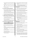
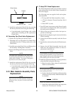
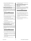
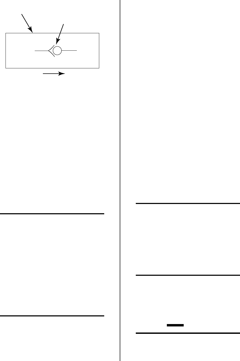
Symbol
Direction Of Flow
Check Valve
A-00370
5. Install the replacement Check Valve by reversing
the above procedure and noting the following:
• Coat the threads of the Fittings with a teflon
sealer before installing on the replacement
Check Valve.
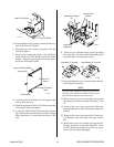
M. Secondary Gas Check Valve Replacement
1. Remove the Top Panel per Section 5.04-B.
2. Disconnect the two Secondary Gas/Water Hose
Assemblies from the T-Fitting connection at the
Check Valve.
3. Carefully remove the Check Valve and Fittings from
the Secondary Gas Regulator Assembly.
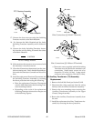
4. Remove the Fittings from the input of the old Check
Valve.
NOTE
The output of the replacement Check Valve should
be pointing away from the Pressure Regulator As-
sembly when installed. The output is designated
by an arrow on the side of the part.
5. Install the replacement Check Valve by reversing
the above procedure and noting the following:.
• Coat the threads of the Fittings with a teflon
sealer before installing on the replacement
Check Valve.
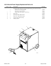
5.10 Main Heatsink Assembly Parts
Replacement
NOTE
Refer to Section 6.09, Main Heatsink Assembly Re-
placement Parts, for parts list and overall detail
drawing.
A. 70 Amp STR. Diode Replacement
The Diode Replacement Kit (Cat # 8-1168) is a direct
parts replacement for the failed Diode Assembly in
the Power Supply.
The following parts are supplied with each replace-
ment assembly:
• 70 Amp, 600V Str Diode Assembly (1 each)
• 0.75 inch diameter Thermal Interface Pad (1
each)
• Tube of RTV (1 each)
1. Turn OFF main input power to the Power Supply
both at the Power Supply ON/OFF switch and at
the main power disconnect.
2. Wait at least two minutes to allow the input ca-
pacitors to discharge.
3. Open the Power Supply to gain access to the faulty
Diode Assembly.
4. Locate the old Diode Assembly inside the Power
Supply.
5. Unsolder the wire lead from the old Diode Assem-
bly.
6. Remove the old Diode Assembly from the unit.
Make sure the replacement diode is a direct re-
placement for the old one.
NOTE
To avoid damage to a replacement diode from over-
heating during installation, a proper heatsink (ex-
ample: alligator clip) must be used to dispurse heat
when soldering the wire lead to the diode.
7. Install the replacement diode by reversing the above
procedure and noting the following:
a Wipe the surface clean where the replacement
diode is to be installed.
NOTE
The thermal interface pads must be properly aligned
when replacing the diode.
b. Position the thermal interface pad between the
diode and contact surface where the diode will
be installed.
CAUTION
Diodes can overheat if not properly installed.
c. Install the replacement diode and torque the
diode to 20 - 25 in-lbs (2.3 - 2.8 Nm).