


Manual 0-2533 31 SERVICE TROUBLESHOOTING
Q. OK-To-Move Tests
1. The Shunt Amp sends a voltage level to the Switch-
ing Control PC Board that corresponds to the work
lead or cutting current. When that current is greater
than 25 amps, a circuit on the Switching Control
PC Board sends an active low signal called CSR to
the Logic PC Board, J3-11, that turns on K1, the
OK-To-Move relay. SW5 on the Logic PC Board
selects whether the OK-To-Move output at J2-14
and 16 is a contact closure (SW5 up) or 24 vac (SW5
down). OK-To-Move from J2-14 and 16 connects
to TB2-9 and 10 then on to J15-10 and 11.
To troubleshoot, while cutting, measure at TB2-9
to TB2-10 for 0 volts both AC and DC indicating
contact closure or if Logic PC Board switch SW5
is set for AC volts measure for 24 VAC.
NOTE
Refer to Appendix XII for OK-To-Move Circuit
Diagram.
If correct go to step 2. If not correct, repeat the
measurement at J2-14 to J2-16. If still incorrect mea-
sure Logic PC Board J3-11 to TP1. If less than 5
vdc replace the Logic PC Board otherwise the
Switching Control PC Board is faulty (or the rib-
bon cable open).
2. If using the Remote Control (RC6010), Logic PC
Board switch SW5 must be up for contact closure,
indicator D104, OK PS, on the Remote Control (RC
6010) internal PC Board should come ON with OK-
To-Move. If not check continuity between TB2-9
and J37-30, also TB2-10 and J37-31. The Remote
Control (RC6010) OK relay is initially energized.
The relay turns OFF to send the OK-To-Move sig-
nal through the relay normally closed contact. As
soon as indicator D104 turns ON, or after the
PIERCE DELAY if the Standoff Control (SC10) is
also used, indicator D102 should go OFF indicat-
ing the OK relay is off. If no Standoff Control
(SC10) is used and indicator D102 does not go OFF,
the Remote Control PC Board is defective. If the
Standoff Control (SC10) is used, set the torch to
proper cutting height manually and disconnect the
Standoff Control (SC10) by removing the ribbon
cable from J5 or J7, and try again. If indicator D102
goes OFF now the Standoff Control PC Board is
faulty (or the ribbon cable is open, pin 11 or 15). If
indicator D102 does not go OFF with the Standoff
Control (SC10) disconnected, the Remote Control
(RC6010) is defective.
3. If indicator D102 goes OFF as it should and the E1
jumper is connected to J6-14 (contacts) measure
for contact closure at J6-13 to 16 or if E1 jumper is
in J6-15 (24 VAC) measure for 24 VAC at J6-13 to
J6-16. If OK, the problem is in the CNC cable con-
nections to the cutting machine or the controller.
4. For the Standoff Control (SC11) refer to Section 5,
Customer/Operator Service, in the Standoff Con-
trol Instruction Manual.
R. Pilot Resistor Adjustment
The amount of pilot current is controlled by the value
of the pilot resistors, R16 and R21. Too much current
causes excessive tip wear and too little causes a sput-
tering pilot that wears the electrode. The factory set-
ting is correct for most cases but with low input line
voltage and with some combinations of gas and tips
the current may be too low to maintain a steady (no
sputtering) pilot.
To adjust the resistors use the following procedure:
1. Remove the left side panel, as viewed from the
front of the unit.
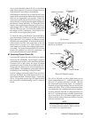
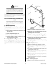
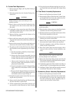
2. Locate and identify the pilot resistors which are
on a bracket in front of the fan.
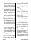
Wire #96
Pilot Resistors
(R16 and R21)
Clamp
Clamp
A-01219
Location Of Pilot Resistors
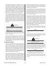
3. Locate wire #96 which is connected between the
two resistors. The wire is attached to each pilot
resistor with a clamp.
4. Using a screwdriver loosen both clamps.
5. Move each clamp down the pilot resistors, toward
the inside of the unit, approximately 1/2 inch (12.7
mm).
6. Test the pilot, if it still sputters move the clamps
another 1/2 inch (12.7 mm).