


Manual 0-2533 37 REPLACEMENT PROCEDURES
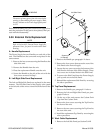
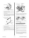
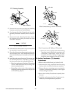
7. Locate and remove the four bolts and lock nuts
securing the Fan Assembly to the Rear Panel As-
sembly.
8. Carefully pull the Fan Assembly from the Rear
Panel Assembly feeding the wiring through the
hole.
9. Install the replacement Fan Assembly by reversing
the above procedure.
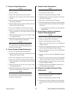
B. Three-Phase Contactor Replacement
1. Remove the Right Side Panel per Section 5.04-B.
2. Note the orientation of all the wires and then dis-
connect the input and output wiring from the
Three-Phase Contactor Assembly.
3. Remove the two locking nuts securing the Three-
Phase Contactor to the Rear Panel of the unit.
4. Install the replacement Three-Phase Contactor As-
sembly by reversing the above procedure.
C. Voltage Selection PC Board Replacement
1. Remove the Right Side Panel per Section 5.04-B.
2. Disconnect all the wiring connections to the Volt-
age Selection PC Board Assembly.
3. Remove the Voltage Selection PC Board from the
four PC Board Standoffs.
4. Install the replacement Voltage Selection PC Board
Assembly by reversing the above procedure.
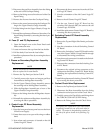
D. Gas Solenoid Assembly Replacement
NOTE
The Plasma and Secondary Gas Solenoid Valve
Assemblies are replaced in the same manner.
1. Remove the Top Panel per Section 5.04-B.
2. Disconnect the Gas Supply at the Rear Panel con-
nection
3. Disconnect the internal Gas Hose Assembly con-
nected to the elbow fitting on the Gas Solenoid
Valve Assembly.
4. Disconnect the two wires connected to the Sole-
noid Valve Assembly.
5. Remove the Panel Nut securing the assembly to
the Rear Panel Assembly.
6. Pull the old Gas Solenoid Valve Assembly from the
Rear Panel Assembly.
7. Install the replacement Solenoid Valve Assembly
by reversing the above procedure and noting the
following:
• Remove the fittings from the old assembly and
install on the replacement assembly.
E. Secondary Water Solenoid Valve Assembly
Replacement
1. Remove the water supply from the Secondary
Water connection at the Rear Panel Assembly.
2. Remove the Top Panel per Section 5.04-B.
3. Disconnect the internal Hose Assembly connected
to the elbow fitting on the Secondary Water
Soleniod Valve Assembly inside the unit.
4. Carefully disconnect the two wire connector to the
Secondary Water Solenoid Valve Assembly.
5. Remove the Panel Nut securing the assembly to
the Rear Panel Assembly.
6. Pull the old Secondary Water Solenoid Valve As-
sembly from the Rear Panel Assembly.
7. Install the replacement Secondary Water Solenoid
Assembly by reversing the above procedure and
noting the following:
• Remove the fittings and Check Valve from the
old assembly and install on the replacement as-
sembly.
F. Rear Panel Coolant Filter Assembly
Replacement
The Coolant Filter Assembly is located on a bracket
on the Rear Panel Assembly of the unit.
1. Remove the two Coolant Hose connections to the
Coolant Filter Assembly.
2. Remove the two elbow fitting on each side of the
Coolant Filter Assembly and remove the damaged
assembly from the bracket.
3. Clean the old thread sealer from the threads of the
elbow fittings.
4. Apply a thin coating of liquid teflon thread sealer
to the threads of the elbow fittings.
5. Place the replacement Coolant Filter Assembly in
the bracket with the arrow pointing to the left and
reinstall the two elbow fittings.
6. Reconnect the two Coolant Hoses to the Coolant
Filter Assembly making sure that the hose to the
Pump Assembly is on the output of the Coolant
Filter Assembly (left side as viewed from the back).