


SERVICE TROUBLESHOOTING 28 Manual 0-2533
The PWM compares shunt amp output on J9-5 with
the current control signal (3.3 - 10 VDC) from the re-
mote (J7-18) or the panel control (J10-15). A faulty
shunt amp could cause the output, normally 0 VDC
with no cutting arc, to go higher, shutting off the PWM
and thus producing no DC. If the shunt amp ribbon
connector is disconnected or pin 1 is open, approxi-
mately 12 VDC is applied to J9-5, shutting down the
PWM in the same manner as a shunt amp failure.
The Switching Control PC Board sends pulses (+15
V) to the Driver PC Board on J8-1 and J8-3. The width
of these pulses controls the on-time of Q1. The pulses
are best observed with an oscilloscope, but an AC
voltmeter should read about 6 to 7 VAC from J8-2 to
both J8-1 and J8-3. If 0 VAC is measured at both J8-1
and J8-3, with the enables (J10-9 and J10-23) and shunt
amp (J9-5) input low, replace the Switching Control
PC Board.
WARNING
Both base and emitter are at -320 VDC potential.
Use extreme caution when testing Driver PC Board
output.
If switching pulses are present at J8-1 and J8-3, check
the Driver PC Board output between J27-3, Q1 base,
and J27-2, Q1 emitter.
The Driver PC Board output, J27-3 (Q1 base) to J27-2
(Q1 emitter), should measure about 1 VAC. If volt-
age measures 0 to -4 VDC (+ lead on J27-3) replace
Driver PC Board. If switching pulses are not present
(start signal OFF), -4 VDC is normal, Driver PC Board
should be replaced.
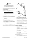
N. Pilot Circuit Check
The pilot is ignited by a high frequency spark gener-
ated in the Arc Starter Box. The Arc Starter Box re-
quires a 24 VAC supply which should always be
present and a torch tip to electrode voltage greater
than 220 vdc. When the PCR contactor closes, power
supply open circuit voltage (280-350 volts) is con-
nected across the torch plus (tip) and minus (elec-
trode). Once the pilot starts the voltage drops to un-
der 220v shutting off the arc starter.
If the front panel PILOT led is on indicating drive to
the PCR contactor but there are no sparks at the spark
gap in the arc starter box, first confirm that there is
open circuit voltage (OCV) of 280-350 vdc between
torch “NEG-” and the work lead then measure the
voltage at the torch bulkhead (marked “NEG-” and
“POS+”). If it is low, zero to 50v, the torch is probably
shorted (pilot resistors will get very hot). If it is be-
tween 100 and 200v PCR contactor is probably not
closing. If it measures the same as the OCV the arc
starter box may be defective.
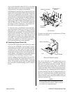
For a shorted torch remove the consumable parts and
check for damage, remove the head from the mount-
ing tube and check for arcing. The short may also be
internal to the head and it may or may not be measur-
able with an ohmmeter. Sometimes the only way to
be sure is replace the head.
If the front panel PILOT indicator is OFF check the
CSR indicator, D5, on the Logic PC Board. It should
be OFF. If it is ON the Switching Control PC Board
may be falsely indicating main arc transfer. Check
for zero volts on the Switching Control PC Board at
J9-5. If it does not measure zero the Shunt Amp which
should have no output is defective. Otherwise the
Switching Control PC Board is faulty. If the Logic PC
Board CSR indicator is OFF and PILOT indicator is
OFF, the Logic PC Board is faulty.
If PILOT indicator is ON and PCR is not closing, check
for 120 VAC between wire #110 and J2-1 on the Logic
PC Board.
NOTE
Refer to Appendix VI for 120 VAC Circuit Dia-
gram.
If not present, replace the Logic PC Board. If 120 VAC
is present, check to see if it is at the PCR coil. If volt-
age is present, the contactor is faulty.
WARNING
High Voltage is present.
For the Arc Starter Box confirm that the OCV mea-
sured at the torch bulkhead is also preset at E1 and E2
on the Arc Starter PC Board, if not the torch leads ex-
tension may be open. Check for 24 VAC from J1-1 to
J1-3 on the Arc Starter PC Board (see note).
NOTE
Later versions of the Arc Starter Box have a 24
VAC indicator on the Arc Starter PC Board. The
indicator will be ON when the 24 VAC is present.
If both OCV and 24 VAC are present, and no sparks
are being generated, the Arc Starter PC Board is de-
fective.