


SERVICE TROUBLESHOOTING 24 Manual 0-2533
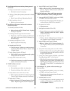
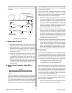
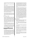
work check continuity from TB2, wires 102 & 103, to
J50-10 & 11. If correct, replace the Switching Control
PC Board.
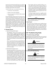
A-01137
K1
RC6010
Switching
Control PCB
ON
ENABLE
To AMP/VOLT
Display Enable
TB2-2
J1-5
J1-4
E2
E3
J37-17
J15-5 J50-12
J50-10
J15-33
J37-27
J37-26
J15-32
TB2-1
J50-11
Merlin 3000, 6000
or 6000GST
+V1
Enable Circuit Diagram
C. Blown Fuse (F1 or F2)
1. A shorted or frozen motor will cause F1 to fail. To
check the motors, disconnect J20 (pump motor)
and J39 (fan motor). Reconnect one at a time to
determine which component is faulty. A shorted
or open fan motor starting capacitor (C32) may
also cause F1 to fail.
2. F2 fuses the 110 VAC circuit. MC1 or MC2, T2, T3
and the gas solenoids are energized when power
is first applied. If shorted, any one of these com-
ponents would cause F2 to fail. W1 or W2, and
PCR energize after the torch switch or remote start
switch is activated. Disconnect all components and
reconnect one at a time to establish which compo-
nent is faulty.
D. Motor Control Contactor Check (MC1 or
MC2)
NOTE
Refer to Appendix VI for 120 VAC Circuit Dia-
gram.
120 VAC is supplied to the Motor Control Contactors
(MC1 and MC2) from the Voltage Selection PC Board,
which selects the proper tap on the Main Transformer
(T1). The return path travels from wire #110 through
the remote connector (J15) on the rear panel to the E-
Stop switch (or if no remote is used, through K1 on
the Switching Control PC Board) to wire #8, through
the ON/OFF switch (SW1A) to wire #9, through fuse
F2 to wire #10 and T1.
Only one of the MC contactors should have voltage
applied. If the red LED indicator (D18) on the volt-
age selection board is lit, MC2 should be energized.
If D18 is not lit, MC1 should be energized.
1. Check the voltage across the coil on the contactor
for approximately 120 VAC. If voltage is present,
replace the contactor. If it is not, perform the 120
VAC test (refer to test paragraph 'A' above) to
check for a proper voltage supply from the volt-
age selection board. If correct, continue to step 2
to isolate the problem in the return path.
2. With one meter lead on the supply side of the con-
tactor coil (wire #3 for MC1 or wire #4 for MC2)
measure to wires #8, 9, and 10 to determine where
the return circuit is broken. On the return path,
F2, SW1-A, and E-Stop can be measured for conti-
nuity. K1 on the switching control board will nor-
mally be open when power is off.
3. When the remote control cable is installed, a jumper
between J15-26 and J15-27 pulls J7-20 on the
switching control board to 0 V (board connector
J7-19). When the jumper is not in place (remote
cable is not plugged in) J7-20 measures +15 VDC
and K1 should energize, bypassing the E-stop func-
tion. If not, replace the switching control board.
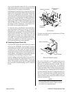
E. Diode Check
There are fourteen diodes in the main heatsink area,
including six large 150 amp input rectifier diodes (D1-
6) and eight small 70 amp diodes (snubbing diodes
D7-10 and freewheeling diodes D11-14). To measure
the resistance of each diode use one of the following:
• An ohmeter set on the Rx1 or Rx10 scale
• Digital meter set to the diode function
Measure the resistance of each diode in both direc-
tions. The readings should differ by at least a factor
of ten. If the readings do not differ (both high or both
low), disconnect one end of the diode and recheck. If
the diode reading is not correct with one end discon-
nected, then replace the diode. Check all diodes be-
fore turning on power to the system.
If a diode fails, check the potential causes of diode
failure to make sure the replacement diode will not
also fail when it is installed:
1. Isolate and check each diode separately to deter-
mine which individual diode has failed.