


REPLACEMENT PROCEDURES 42 Manual 0-2533
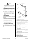
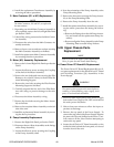
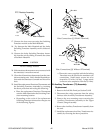
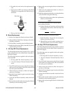
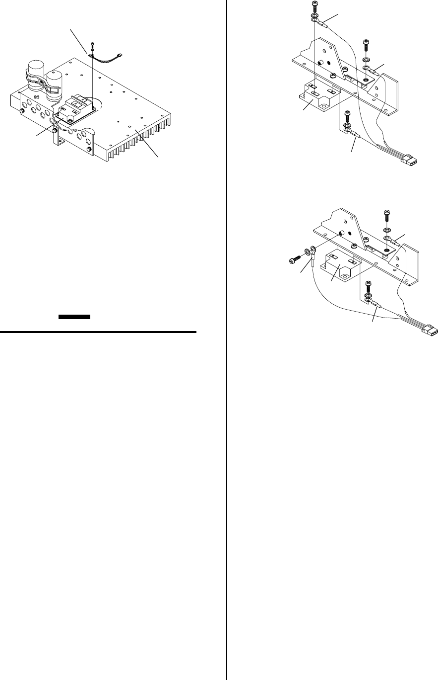
PTC Resistor Assembly
Q1
Main Heatsink
A-01089
17. Remove the four screws securing the Switching
Transistor module to the Main Heatsink.
18. Pry between the Main Heatsink and the faulty
Switching Transistor Assembly until it slides eas-
ily.
19. Remove the faulty Switching Transistor Assem-
bly from the unit by sliding it towards the center
of the Main Heatsink.
CAUTION
DO NOT damage Heatsink.
20. If the transistor thermstrate was not removed with
the transistor, it must be removed.
21. Clean the old transistor thermstrate from the tran-
sistor mounting area. Verify that the Heatsink sur-
face under the transistor is smooth and free of de-
fects.
22. Install the replacement Transistor Thermstrate and
the Switching Transistor Assembly by reversing
the above procedure and noting the following:
• Place the replacement Transistor Thermstrate
onto the Main Heatsink at the Switching Tran-
sistor mounting location.
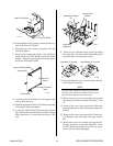
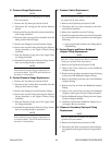
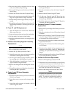
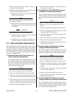
• Depending on the style of the replacement
Switching Transistor connect the wires per one
of the following Figures:
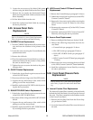
B
BX
Wire #83
Wire #82
Wire #84
Q1
E
A-01086
Wire Connections (Q1 With E Terminal)
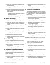
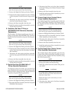
B
BX
Wire #83
Wire #82
Wire #84
Q1
A-01087
Wire Connections (Q1 Without E Terminal)
• The metric screws supplied with the Switching
Transistor are to be used for the transistor wire
connections. Small metric screws are to be
torqued to 12 in-lbs (1.4 Nm). Larger metric
screws are to be torqued to 26 in-lbs (2.9 Nm).
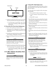
B. Auxiliary Transformer (T3) Assembly
Replacement
1. Remove the Left Side Panel per Section 5.04-B.
2. Disconnect the wiring connector from the wiring
harness at the Auxiliary Transformer Assembly.
3. Remove the two mounting screws securing the
Auxiliary Transformer Assembly to the Upper
Chassis/Gauge Assembly.
4. Remove the Auxiliary Transformer Assembly from
the unit.
5. Install the replacement Auxiliary Transformer As-
sembly by reversing the above procedure.