


REPLACEMENT PROCEDURES 36 Manual 0-2533
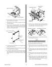
3. Remove the Coolant Hose from the Internal Cool-
ant Filter Assembly.
4. Remove the Internal Coolant Filter from the fitting
on the Radiator.
5. Install the replacement Internal Coolant Filter As-
sembly by reversing the above procedure and not-
ing the following:
• Clean the old thread sealer from the threads of
the hose and the fitting.
• Apply a thin coating of liquid teflon thread
sealer to the threads of the fitting.
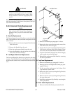
B. Radiator Replacement
1. Remove the Left and Right Side Panels per Section
5.04-B.
2. On the right side of the radiator locate the Hose
Assembly connected to the input of the Radiator
at the top.
3. Remove the Hose Assembly from the Radiator in-
put connection.
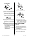
4. Remove the Internal Coolant Filter per paragraph
'A' above.
5. On the top and bottom of the Radiator remove the
six screws and star washers that secure the Radia-
tor to the Front Panel.
6. Carefully slide the Radiator out of the unit.
7. Install the replacement Radiator by reversing the
above procedure.
C. Bias PC Board Replacement
1. Remove the Right Side Panel per Section 5.04-B.
2. Disconnect all the wiring connections to the Bias
PC Board Assembly.
3. Remove the Bias PC Board Assembly from four PC
Board Standoffs.
4. Install the replacement Bias PC Board Assembly
by reversing the above procedure.
D. Transformer (T2) Assembly Replacement
The Tramsformer (T2) Assembly is mounted to the
rear of the Horizontal Chassis Panel and has 25.2 VCT
(Center Tap) output.
1. Remove the Left Side Panel per Section 5.04-B.
2. Disconnect all the wiring connections to the Trans-
former Assembly.
3. Remove the four screws which secure the Trans-
former Assembly to the Horizontal Chassis Panel.
4. Carefully remove the Transformer Assembly from
the unit.
5. Install the replacement Transformer Assembly by
reversing the above procedure.
E. Internal Fuse (F3) Replacement
The Fuse (F3) is located inside the Power Supply be-
hind the Right Side Panel. The Fuse is mounted next
to the Bias PC Board on the rear of the Horizontal
Chassis Panel.
1. Remove the Right Side Panel per Section 5.04-B.
2. Locate the Fuse mounted next to the Bias PC Board
on the Horizontal Chassis Panel.
3. Remove the damaged Fuse from the snap type fuse
holder.
4. Reinstall the replacement Fuse (1A, 250V) by re-
versing the above procedure.
F. Fuse Holder (Internal) Replacement
1. Remove the Left Side Panel per Section 5.04-B.
2. Remove the Fuse from the holder.
3. Disconnect the two wires connected to the Fuse
Holder.
3. Remove the two small screws securing the Fuse
Holder to the chassis.
4. Install the replacement Fuse Holder by reversing
the above procedure.
5.07 Rear Panel Parts Replacement
NOTE
Refer to Section 6.06, Rear Panel Parts Replace-
ment, for parts list and overall detail drawing.
A. Fan Replacement
1. Remove the Left Side Panel per Section 5.04-B.
2. Locate the Fan Assembly wiring connector inside
the Rear Panel.
3. Carefully disconnect the wiring connector from the
wiring harness.
4. Note the pin location of each wire to the connector.
5. Using a pin extraction tool remove the wiring from
the connector.
6. On the Rear Panel remove the strain relief securing
the Fan Assembly wiring to the Rear Panel.