


Manual 0-2533 43 REPLACEMENT PROCEDURES
C. Pressure Gauge Replacement
NOTE
Both the Plasma and Secondary gauges are replaced
in the same manner
1. Remove the Top Panel per Section 5.04-B.
2. Disconnect the wiring tho the desired Pressure
Switch.
3. Remove the Pressure Switch from the desired Pres-
sure Gauge Assembly.
4. Disconnect the input gas Hose Assembly from the
fitting at the Pressure Gauge.
5. Remove the fitting(s) from the Pressure Gauge.
6. Remove the nut and clamp Securing the Pressure
Gauge Assembly to the Upper Chassis/Gauge
Assembly.
7. Slide the Pressure Gauge out of the Upper Chas-
sis/Gauge Assembly.
8. Reinstall the replacement Pressure Gauge Assem-
bly by reversing the above procedure.
NOTE
Be sure that the Pressure Gauge orientation is cor-
rect when installed. The 80 PSI mark should be at
the twelve o'clock position.
D. Coolant Pressure Gauge Replacement
1. Remove the Top Panel per Section 5.04-B.
2. Disconnect the Coolant Hose Assembly from the
fitting at the Pressure Gauge.
3. Remove the fitting(s) from the Pressure Gauge.
4. Remove the nut and clamp Securing the Pressure
Gauge Assembly to the Upper Chassis/Gauge
Assembly.
5. Slide the Pressure Gauge out of the Upper Chas-
sis/Gauge Assembly.
6. Reinstall the replacement Pressure Gauge Assem-
bly by reversing the above procedure.
NOTE
Be sure that the Pressure Gauge orientation is cor-
rect when installed. The 80 PSI mark should be at
the twelve o'clock position.
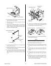
E. Pressure Switch Replacement
NOTE
Both the Plasma and Secondary Pressure Switches
are replaced in the same manner
1. Remove the Top Panel per Section 5.04-B.
2. Disconnect the two wires connected to the Pres-
sure Switch Assembly.
3. Remove the assembly from the T-fitting.
4. Install the replacement Pressure Switch Assembly
by reversing the above procedure and noting the
following:
• Apply pipe thread sealant to the fitting before
reassembling.
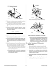
F. Coolant Supply and Return Bulkhead
Adapter Fitting Replacement
NOTE
Both the Coolant Supply and Return Bulkhead
Fittings are replaced in the same manner.
1. Remove the Top Panel per Section 5.04-B.
2. Remove the Torch connection to the Bulkhead
Adapter Fitting.
3. Disconnect the gas Hose Assembly from the fitting
at the end of the Bulkhead Adapter Fitting.
4. Remove the fittings from the end of the Bulkhead
Adapter Fitting.
5. Remove the first nut from the Bulkhead Adapter
Fitting.
6. Remove the second nut securing the Bulkhead
Adapter to the Upper Chassis/Gauge Assembly.
7. Pull the Bulkhead Adapter Fitting from the Upper
Chassis/Gauge Assembly.
8. Install the replacement Bulkhead Adapter by re-
versing the above procedure.
G. Plasma or Secondary Gas Input Fitting
Replacement
NOTE
Both the Plasma and Secondary Gas fittings are
replaced in the same manner
1. Remove the Top Panel per Section 5.04-B.
2. Disconnect the Torch connection to the fitting be-
ing replaced at the Upper Chassis/Gauge Assem-
bly.