


REPLACEMENT PROCEDURES 44 Manual 0-2533
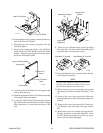
3. Disconnect the gas Hose Assembly from the fitting
at the end of the Gas Input Fitting.
4. Remove the fitting screwed into the end of the Gas
Input Fitting.
5. Remove the first nut from the Gas Input Fitting.
6. Remove the second nut securing the Gas Input Fit-
ting to the Upper Chassis/Gauge Assembly.
7. Pull the fitting from the Upper Chassis/Gauge As-
sembly.
7. Reinstall the replacement Plasma or Secondary Gas
Input Fitting Assembly by reversing the above pro-
cedure.
H. Fuse (F1 and F2) Replacement
1. Open the hinged cover at the Front Panel torch
leads connection area.
2. Locate and remove the cap from the fuse holder.
3. Pull the faulty Fuse from the fuse holder.
4. Install the replacement Fuse by reversing the above
procedure.
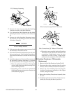
I. Plasma or Secondary Regulator Assembly
Replacement
NOTE
Both the Plasma and Secondary Regulator Assem-
blies are replaced in the same manner
1. Remove the Top Panel per Section 5.04-B.
2. Carefully remove the input and output gas Hose
Assemblies to the Regulator Assembly.
3. On the Upper Ghassis/Gauge Assembly remove
the securing nut for the Regulator Assembly.
4. Slide the Regulator Assembly.out of rear of the
Upper Ghassis/Gauge Assembly.
5. Remove the fittings from the old Regulator Assem-
bly.
6. Reinstall the replacement Regulator Assembly by
reversing the above procedure.
J. Control Logic PC Board Assembly
Replacement
1. Open the front panel access panel cover at the front
of the Power Supply.
2. Fasten the access cover open with string or rubber
band.
3. Note where each connector is located on the old
Control Logic PC Board.
4. Disconnect the three connectors from the old Con-
trol Logic PC Board.
5. Note the orientation of the old Control Logic PC
Board.
6. Remove the old Control Logic PC Board.
7. On the new Control Logic PC Board set the
switches, SW1 through SW5, the same as the old
Control Logic PC Board.
8. Install the replacement Control Logic PC Board by
reversing the above procedure.
K. Switching Control PC Board Assembly
Replacement
1. Remove the Top and Right Side Panels per Section
5.04-B.
2. Note the orientation of the old Switching Control
PC Board.
3. Remove the Switching Control PC Board from the
rear of the Upper Chassis/Gauge Panel far enough
to disconnect the wiring connections.
4. Note where each connector is located on the Switch-
ing Control PC Board.
5. Disconnect the connectors from the Switching Con-
trol PC Board.
6. Reconnect the original wiring connectors to the
replacement Switching Control PC Board before
installing the replacement Switching Control PC
Board.
7. Install the replacement Switching Control PC Board
by reversing the above procedure.
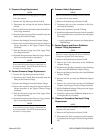
L. Coolant Check Valve Replacement
1. Remove the Top Panel per Section 5.04-B.
2. Disconnect the Hose Assemblies from the fitting
connection at the input end of the Check Valve.
3. Carefully remove the Check Valve and fittings from
the TORCH COOLANT SUPPLY fitting.
4. Remove the Fittings from the old Check Valve.
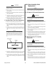
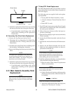
NOTE
The input of the replacement Check Valve should
be pointing towards the rear of the unit when in-
stalled. The output is designated by a symbol on
the side of the part as shown in the following Fig-
ure.