


Manual 0-2533 17 SERVICE TROUBLESHOOTING
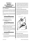
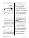
C. Switch-Mode Power Supply Operation
Primary three-phase power is rectified by the three-
phase bridge diodes D1-D6. The resulting negative
DC voltage (approximately -320 VDC) is applied to
the switching transistor (Q1). The switching transis-
tor controls the output current by pulse width modu-
lation (PWM). PWM varies the duty cycle (or on-time
versus off-time) of the switch. The greater the on-time,
the higher the output current will be. Components
D7-10, R2-3, C13-14, L1, and the Suppression PC Board
are snubbers to limit voltage and current surges caused
by switching Q1 on and off. D11-14 are free wheeling
diodes. When Q1 is on, current flows through Q1 into
the output network. When Q1 is off, D11-14 provide
a path for current to continue flowing supported by
energy that was stored in the output network during
the time Q1 was on. The switching transistor output
is a series of pulses which are filtered back into pure
DC voltage by the output network. The output net-
work consists primarily of the main inductor (L2A and
L2B), resistor R13, and capacitor C23.
D. Switching Control PC Board
The Switching Control PC Board compares the shunt
amp output with the current control pot setting and
generates logic level PWM signals. The shunt and
Shunt Amp PC Board are located between the input
bridge positive and work lead to measure the output
cutting current. The signals are sent to the driver PC
board, where they are converted into the current and
voltage levels needed to drive the switching transis-
tor.
The Switching Control PC Board senses if the Remote
Control (RC6010) is installed to route the current con-
trol signal from the remote instead of the Merlin front
panel control. The Switching Control PC Board routes
the Shunt Amp signal to the remote’s current display,
sends a torch voltage signal to the standoff control
and supplies POT HI and POT LOW signals to set
min and max output to both remote and front panel
current controls. CSR (output greater than 25A) and
over current shutdown (current greater than 175A)
are sent to the Logic PC Board.
A relay on the Switching Control PC Board, controled
by the Remote Control (RC6010) ENABLE switch or
the ENABLE input on TB2, removes power from one
side of the motor (MC) and main (W) contactors coils
when the enable switch is off shutting off the coolant
flow and DC power to allow changing torch parts.
E. Logic PC Board Functions
The Logic PC Board controls the timing and sequenc-
ing of the system. It monitors the pressure, tempera-
ture, and flow interlocks and controls the gas flow in
run, set, and purge modes by turning on the plasma
and secondary solenoids. The Logic PC Board also
controls pre-flow and post-flow durations, which are
selectable by DIP switches on the board. The Logic
PC Board drives the sequence status LED indicators
and contains the circuit for measuring coolant con-
ductivity.
After receiving the CNC (cutting machine controller)
START signal from either the remote control, the
standoff control, direct from the controller via the re-
mote connector or TB2 the “simple” interface termi-
nal strip, the Logic PC Board initiates gas preflow then
energizes the main contactor, W1 or W2 (as deter-
mined by the Voltage Selection PC Board).
The Logic PC Board closes the pilot contactor and
sends enable signals to the Switching Control PC
Board to start the PWM and turn on the main switch-
ing circuits producing open circuit output voltage
(OCV). When the Arc Starter Box senses OCV greater
than 220 V between the Torch plus (+) and minus (-) it
starts the CD (capacitor discharge) arc starting circuit
to fire the spark gap producing the high voltage spark
which starts the DC pilot arc. Once a constant DC
pilot is established the torch voltage drops below 220
V and shuts off the CD circuit. When the Torch is
close to the work the cutting arc “transfers” to the
work.
The resulting current in the work lead is sensed by
the Shunt Amp and the Switching Control PC Board
sends the CSR signal to the Logic PC Board which
opens the pilot contactor shutting off the pilot anf
generating an “OK-To-Move” signal. OK-To-Move
can be either contact closure or 24VAC through con-
tacts selected by switch SW5 on the Logic PCB. OK-
To-Move is sent to the remote control, the standoff
control or directly to the cutting machine controller.
It controls the optional High Flow Water Shield and
the Arc Hour/Starts Counter.
F. LED/Current Control PC Board
The LED and current control PC board contains the
sequence status LED indicators and the front panel
current control pot.
G. Remote Control
The Remote Control allows remotely controlling the
cutting current, setting reduced current for corner
slowdown, and enabling gas purge and set functions.
An ENABLE switch shuts down the power supply and
coolant pump for changing torch consumables. The
Digital Amperage display allows accurate setting and
monitoring of the cutting current. Connections to the
cutting machine controller (CNC) are electrically iso-
lated to minimize interference. Both a rear panel con-