


Manual 0-2533 35 REPLACEMENT PROCEDURES
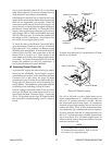
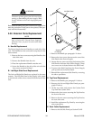
2. Loosen the two screws of the Work Cable strain
relief securing the Work Cable at the Front Panel.
3. Remove the nut (under the Horizontal Chassis
Panel) securing the Work Cable connection to the
Shunt Assembly.
4. Pull the Work Cable from the unit.
5. Install the replacement Work Cable by reversing
the above procedure.
5.05 Access Panel Parts
Replacement
NOTE
Refer to Section 6.04, Access Panel Replacement
Parts, for parts list and overall detail drawing.
A. CURRENT Knob Replacement
1. Turn the CURRENT adjustment fully counter clock-
wise and note the location of the pointer on the
knob.
2. Loosen the screw securing the Current Knob to the
potentiometer shaft.
3. Remove the old knob.
4. Place the replacement Current Knob on to the po-
tentiometer shaft with the location of the pointer
the same as noted in step 1.
5. Tighten the screw to secure the knob to the poten-
tiometer shaft.
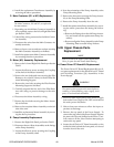
B. ON/OFF Switch Replacement
1. Unlatch the Access Panel to gain access to the rear
of the ON/OFF Switch.
2. Disconnect all the wiring to the ON/OFF Switch.
3. Squeeze the top and bottom of the switch while
pulling it out of the Access Panel
4. Install the replacement ON/OFF Switch by revers-
ing the above procedure.
C. RUN/SET/PURGE Switch Replacement
1. Unlatch the Access Panel to gain access to the rear
of the RUN/SET/PURGE Switch.
2. Disconnect all the wiring to the RUN/SET/PURGE
Switch.
3. Squeeze the top and bottom of the switch while
pulling it out of the Access Panel
4. Install the replacement RUN/SET/PURGE Switch
by reversing the above procedure.
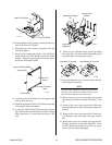
D. LED/Current Control PC Board Assembly
Replacement
1. Remove the Current Knob per paragraph 'A' above.
2. Unlatch the Access Panel to gain access to the LED/
Current Control PC Board.
3. Remove the four screws and washers securing the
LED/Current Control PC Board to the Access
Panel.
4. Disconnect the connector at J5 of the LED/Current
Control PC Board.
5. Install the replacement LED/Current Control PC
Board by reversing the above procedure.
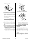
E. Access Panel Replacement
1. Remove the Right Side Panel per Section 5.04-B.
2. Remove the following components from the Ac-
cess Panel:
• Current Knob per paragraph 'A' above.
• ON/OFF Switch per paragraph 'B' above.
• RUN/SET/PURGE Switch per paragraph 'C'
above.
• LED/Current Control PC Board per paragraph
'D' above.
3. Remove the four screws securing the Access Panel
to the LED/Current Control PC Board standoffs.
4. Install the replacement Access Panel by reversing
the above procedure.
5.06 Front Panel/Chassis Parts
Replacement
NOTE
Refer to Section 6.05, Front Panel/Chassis Replace-
ment Parts, for parts list and overall detail draw-
ing.
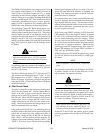
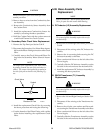
A. Internal Coolant Filter Replacement
The Internal Coolant Filter Assembly is located inside
behind the Left Side Panel (viewed from the front of
the unit). The filter is attached to the Radiator inside
of the Lower Front Panel.
1. Remove the Left Side Panel from the Power Sup-
ply per Section 5.04-B.
2. Locate the Internal Coolant Filter near the front of
the unit.