


Manual 0-2533 39 REPLACEMENT PROCEDURES
CAUTION
Handle and dispose of the used coolant per recom-
mended procedures.
3. Remove the two wires from the Conductivity Sen-
sor Assembly.
4. Remove the Conductivity Sensor Assembly from
the Coolant Tank.
5. Install the replacement Conductivity Sensor As-
sembly by reversing the above procedure.
6. Refill the Coolant Tank with the coolant removed
or add fresh Thermal Arc Torch Coolant.
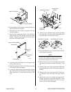
J. Secondary Water Check Valve Replacement
1. Remove the Top Panel per Section 5.04-B.
2. Disconnect the Secondary Gas/Water Hose Assem-
bly from the Elbow Fitting connection at the Check
Valve.
3. Carefully remove the Check Valve and Elbow Fit-
ting from the Secondary Water Solenoid Assem-
bly.
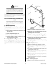
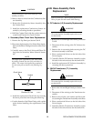
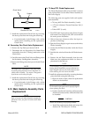
NOTE
The output of the replacement Check Valve should
be pointing towards the rear of the unit when in-
stalled. The output is designated by a symbol on
the side of the part as shown in the following Fig-
ure.
Symbol
Direction Of Flow
Check Valve
A-00370
4. Install the replacement Check Valve by reversing
the above procedure and noting the following:
• Coat the threads of the Elbow Fitting with a teflon
sealer before installing the replacement Check
Valve.
5.08 Base Assembly Parts
Replacement
NOTE
Refer to Section 6.07, Base Assembly Replacement
Parts, for parts list and overall detail drawing.
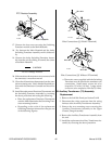
A. DC Inductor (L2) Assembly Replacement
WARNING
The removal of this Assembly requires the use of a
mechanical lift.
1. Remove the Left and Right Side Panels per Section
5.04-B.
2. Disconnect all the wiring at the DC Inductor As-
sembly.
3. Remove the six mounting bolts securing the DC
Inductor Assembly to the Base.
4. Place a mechanical lift next to the left side of the
Power Supply.
5. Carefully slide the DC Inductor Assembly out the
left side of the unit and onto the mechanical lift.
6. Install the replacement DC Inductor Assembly by
reversing the above procedure
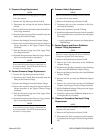
B. 29KVA Transformer (T1) Assembly
Replacement
WARNING
The removal of this Assembly requires the use of a
mechanical lift.
1. Remove the Left and Right Panels per Section 5.04-
B.
2. Disconnect all the wireing at the Transformer As-
sembly.
3. Remove the six bolts, star washers and flat wash-
ers securing the Transformer Assembly to the Base.
4. Place a mechanical lift next to the left side of the
Power Supply.
5. Carefully slide the Transformer Assembly out the
left side of the unit and onto the mechanical lift.