


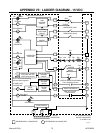
APPENDIX 68 Manual 0-2533
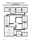
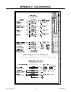
APPENDIX II: SEQUENCE OF OPERATION
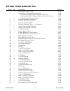
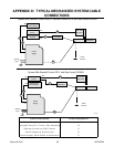
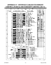
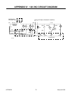
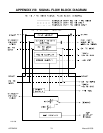
BLOCK DIAGRAM
A-01016
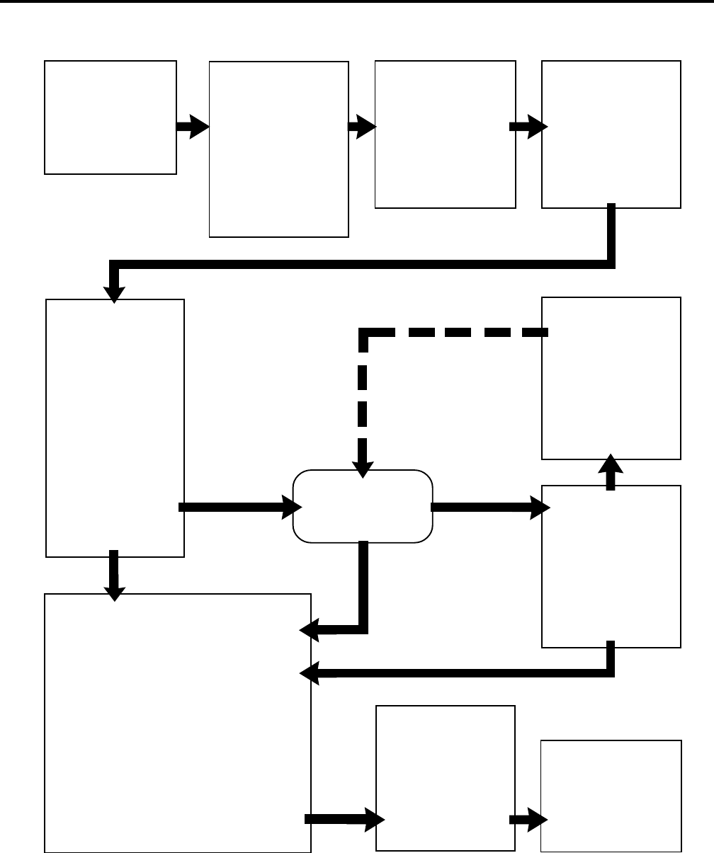
ACTION
Close external
disconnect switch
RESULT
• Power to system
ACTION
Enable ON at Remote
or TB2
ON/OFF switch to ON
RESULT
• AC indicator ON
• TEMP Indicator ON
• GAS indicator ON
• Fan and pump ON
• 40 second auto-purge
ACTION
RUN/SET/PURGE
switch to SET
RESULT
• Gas solenoids open,
gases flow to set
pressures
• GAS indicator ON
ACTION
RUN/SET/PURGE
switch to RUN
RESULT
• Gas flow stops
• Power circuit ready
• GAS indicator OFF
ACTION
Protect eyes and
activate torch
RESULT
• Gas indicator ON
• Gas pre-flow
• Main contactor
closes
• DC indicator ON
• Pilot contactor
closes
• PILOT indicator ON
• Pilot arc established
PILOT ARC
ACTION
Torch de-activated by torch switch
released or remote device
RESULT
• Main arc stops
• Main contactor opens
• DC indicator OFF
• Pilot and PILOT indicator OFF
NOTE- If torch is activated during post-flow
the pilot arc will immediately restart. If
within range of work, main arc will transfer.
After post-flow:
• Gas solenoids close, gas flow stops
• GAS indicator OFF
ACTION
ON/OFF switch to
OFF
RESULT
• AC indicator OFF
• TEMP Indicator OFF
• Fan and pump OFF
ACTION
Open external
disconnect
RESULT
• No power to system
ACTION
Torch moved to
within
1/8 - 3/8 inch of
work
RESULT
• Main arc transfer
• PILOT indicator OFF
• Pilot arc OFF
ACTION
Torch removed from
work
RESULT
• Main arc stops
• Pilot arc auto-restart
• PILOT indicator ON