


Manual 0-2533 25 SERVICE TROUBLESHOOTING
2. High frequency protection for the input rectifier
diodes (D1-6) is provided by capacitors C1 - C6
and MOV 1-3, which are located between each side
of the diode heatsink on the input filter PC board.
Except for the shorts, these components can not
be checked with a volt/ohm meter. To be safe, the
complete input filter board should be replaced any
time an input diode fails.
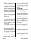
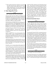
3. Diodes can overheat if air flow over the heatsink is
not adequate or if the diode is not properly fas-
tened to the heatsink. Check that all small diodes
(D7-14) are torqued to 20-25 in-lbs (2.3-2.8 Nm)
and all large diodes (D1-6) are torqued to 34 in-lbs
(3.8 Nm). Apply a light film of electrically con-
ductive heatsink compound between the diode
and heatsink. Make sure air passages in and out
of the unit are not obstructed.
4. Diodes that are faulty at the time of manufacture
are difficult to diagnose. These diodes generally
fail within the first few hours of operation. Before
deciding that this was the case, be sure to check
out other possibilities.
F. Thermal Sensing Circuit Check
1. Thermal sensors TS1, TS2, TS3, TS4, and TS5 are
connected in series to J1-9 on the Logic PC Board.
TS2 is a PTC resistor whose resistance varies with
temperature from about 100 ohms at room tem-
perature (68°F/20°C) to 3.3K at 140°F (60°C) switch
point. TS1, TS3, TS4 and TS5 are switches nor-
mally closed, 0 ohms, that open at over tempera-
ture. TS1, TS4 and TS5 are part of the Main Trans-
former Assembly. TS2 is on the Heatsink and TS3
is on the Pilot Resistor.
Check the voltage from J1-9 to test point TP1 (or
J1-8) on the Logic PC Board for less than 7.5 VDC.
If the voltage is greater than 7.5 VDC, the unit is
overheated or a temperature sensor is faulty.
2. If the unit still operates but the TEMP indicator is
red, the problem may be on the LED PC board. If
the voltage is less than 7.5 VDC, check the voltage
from J3-4 to test point TP1 (ground). If the voltage
is greater than +4 VDC (and the TEMP indicator
is lit red), replace the LED PC board. If the volt-
age at J3-4 is less than 4V, replace the Logic PC
Board.
G. Pressure Sensing Circuit
Pressure switches PS1 and PS2 are connected in se-
ries to J1-7 on the Logic PC Board. PS2 is jumpered
out by SW3-B when the unit is set to the O2 (no sec-
ondary gas) or water secondary mode or by SW2-B in
the GC3000 Gas Control if that option is installed.
1. Check the voltage at J1-7 for less than 1 VDC with
gases flowing and operating pressure greater than
35 psi (2.4 BAR).
2. If the voltage at J1-7 is less than 1 VDC, check the
voltage at J3-3. If the voltage at J3-3 is greater than
12 VDC, replace the Logic PC Board. If the volt-
age at J3-3 is less than 12 VDC, replace the LED
PC Board.
H. Gas Solenoid Circuits
1. Set the RUN/SET/PURGE switch to SET position.
Measure continuity between the center terminal
of the switch (wire #62) and each outer terminal
(wires #61 and 63). If the resistance is less than
1000 ohms, replace the RUN/SET/PURGE switch.
2. If the resistance is greater than 1000 ohms, apply
power and check for 120 VAC between wire #110
and J2-3 for plasma and J2-7 for secondary. If 120
VAC is present at one point and not the other, re-
place the Logic PC Board.
3. If no voltage is present at J2-3 or at J2-7, check for
120 VAC at J2-5 (the Logic PC Board input). If 120
VAC is present at J2-5, replace the Logic PC Board.
If not, check the 120 VAC voltage supply (refer to
Section 4.05-A, Voltage Selection PC Board Check).
I. Coolant Flow Sensor Circuit Check
The flow sensor (FS1) for the coolant is calibrated for
0.25 gpm (1.1 lpm). When adequate coolant flow sat-
isfies FS1 it closes, connecting J1-5 on the Logic PC
Board to J1-4 (common).
Measure voltage between J1-5 and J1-4 or TP1. If J1-5
is greater than 1 volt, FS1 or connections to FS1 are
faulty. If J1-5 measures close to 0 VDC, check J3-2. If
J3-2 measures less than +12 VDC, and the coolant flow
indicator is not lit, replace the LED PC board. If J3-2
measures greater than +12 VDC, replace the Logic PC
Board.
J. Coolant Conductivity Circuit
The conductivity probe consists of two insulated pins
that extend into the coolant reservoir. The Logic PC
Board sends out an AC voltage level on J2-24 that
varies with the conductivity of the coolant.
1. Disconnect one of the wires to the conductivity
probe (wire #57 or 58). The Logic PC Board will
see infinite resistance and the coolant conductiv-
ity LED indicator should be lit. If the coolant con-
ductivity indicator is lit, replace the coolant. If the
problem remains after coolant is changed, replace
the conductivity probe.