


Manual 0-2533 27 SERVICE TROUBLESHOOTING
lem is in the Standoff Control (SC10) or the ribbon
cable. Refer to Section 5, Customer/Operator Service,
in the Standoff Control Instruction Manual.
If the Standoff Control (SC10) isn’t used or the Power
Supply didn’t start with the ribbon cable disconnected,
there are two approaches you can take. Either dis-
connect the remote and see if the Power Supply will
start without it or check if the start signal is getting to
the Remote Control (RC6010). To check the Power
Supply, remove the remote connector at J15 and con-
nect a jumper TB2-1 to TB2-2 for ENABLE, then jump
TB2-3 to TB2-4 for start. If it starts the problem is in
the remote or CNC connections. If not refer to Sec-
tion 4.05-K, Power Supply Start Circuit.
To check for start to the Remote Control (RC6010),
open the Remote Control cover and see if indicator
D103 comes ON. If so, problem is in Remote control
(RC6010) or the remote cable. If indicator D103 is OFF,
remove J29 (or the CNC start connections to J6) and
jumper J29-3 to 4 or J6-3 to 4. Don’t jumper to the
screw heads on J6 as they don’t always make electri-
cal contact. If it starts (indicator D103 ON) with the
jumper, the problem is in the CNC connections. If
not, replace the Remote Control (RC6010).
M. Switching Control Check (Q1)
To produce DC output, the main switch (Q1) must be
turned on and off rapidly. Power Supply output is
controlled by the on-time. At the same time the Main
Contactor (W1 or W2) closes, the Logic PC Board
grounds pins 9 and 23 of the 34-pin ribbon cable (J3-9
on the Logic PC Board, J10-9 on the Switching Con-
trol PC Board). This enables the pulse width modula-
tor (PWM) on the Switching Control PC Board.
If no DC voltage is detected within 75 ms at J1-24 on
the Logic PC Board, the enable signal on J10-9 is re-
moved and the Main Contactor opens. Connecting
TP4 to TP1 (ground) on the Logic PC Board disables
this function for troubleshooting if no DC output is
found.
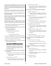
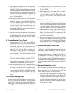
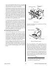
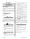
Switching Transistor
Q1
Large Blue
Capacitors
A-01085
Transistor/Coil
Bracket
Q1 Location
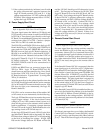
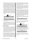
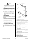
To check for a defective Q1, first disconnect J27 from
the Driver PC Board.
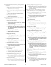
Driver PC Board
Rear of Front Panel
A-01083
Driver PC Board Location
On a X1 or X10 scale or with a digital meter set for
diode, measure between “C” (collector) terminal, wire
#83, and “E” (emitter) terminal, wire #84. Reverse
the meter leads and measure again. It is normal to
measure an open (high reading) one way and a lower
reading the other. A low or zero measurement both
ways means the Q1 is shorted and must be replaced.
If correct, measure from the “B” (base) terminal, wire
#82, to “E” (emitter) terminal, wire #84. Normal read-
ing is from about 50 to 150 ohms (digital meter on
ohms not diode scale) a short (zero ohms) or an open
indicates a defective Q1.
NOTE
If the Switching Control Q1 has failed, the Driver
PC Board must also be replaced. Refer to Section
6.08, Item #2, for replacement parts.