


Manual 0-2533 29 SERVICE TROUBLESHOOTING
If 24 VAC is not present, remove J14 control connec-
tor at the torch bulkhead and measure for 24 VAC be-
tween pins 5 and 8 of the receptacle. The 24 VAC
comes from T3, is fused by F3, 1A 250v, and passes
through the filter FL1 to J14. If voltage is not present
at J14 the most likely fault is the fuse. T3 and the FL1
are other possibilities. If F3 is blown replace it and
leave J14 disconnected. If it doesn’t blow, then recon-
nect J14. If fuse blows again then the Arc Starter PC
Board is defective or there is a short in the torch leads
between J14 and the Arc Starter PC Board.
O. Current Control, Display and CSD checks
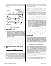
1. Tip Drag Circuit
The Merlin 3000 has a circuit that monitors the
torch tip voltage to reduce cutting current to 40-
50 amps reducing consumable parts wear if the
tip voltage is less than -20 volts indicating double
arcing or the tip contacting the work. Wire #7 from
the torch bulkhead (+) connection connects to the
Logic PC Board at terminal W7. If the voltage there
is less than -20 VDC the Logic PC Board puts a
low on J3-25 (can measure at TP5 on the Logic PC
Board) causing the Switching Control PC Board
(J10-25) to reduce the current. When piloting or
cutting the tip voltage at W7 should be greater than
-20 volts, if so and Logic TP5 is low the Logic PC
Board is defective.
2. Front Panel Current Control
If the Remote Control (RC6010) is being used the
front panel control is inactive, go to next step.
The front panel current control receives it’s high
level (10 VDC) on J10-17 and it’s low level (3.3
VDC) on J10-13. Verify those voltages (with re-
spect to TP1 on the Switching Control PC Board)
then measure the pot’s wiper between J10-15 and
TP1. It should vary from 3.3 to 10 VDC as the
control is moved from minimum to maximum. If
it does not vary or is less than 3.3 VDC, then the
control pot in the LED PC Board is faulty or the
ribbon cable is faulty. If the high and low (3.3 VDC
and 10 VDC) are incorrect, the Switching Control
PC Board is faulty or the ribbon cable is shorted.
3. Remote Current Control
NOTE
Refer to Appendix X for Current Control Display
Circuit Diagram.
The Remote Control (RC 6010) has front panel
controls for OUTPUT AMPS and CSD. The up-
per and lower limits of the current control range
are set by the POT HI (+10 VDC) and POT LOW
(+3.3 VDC) signals from J50-8 and J50-6 on the
Switching Control PC Board sent to the remote via
the remote cable.
The CSD control upper limit is set by the wiper of
the OUTPUT AMPS control thus the CSD range is
a percentage (%) of the main output. The wiper
of the main pot is sent through the normally closed
CSD relay contact out the remote cable to J7-18 on
the Switching Control PC Board. If CSD is en-
abled, indicated by illuminating the 3 decimals in
the display, then the CSD wiper provides the cur-
rent control signal to J7-18.
NOTE
Refer to Appendix XI for Corner Slowdown (CSD)
Circuit Diagram.
If the OUTPUT AMPS control or the CSD control
have no effect on current level see if the panel con-
trol does, if so, there may be a poor connection in
the REMOTE INSTALLED circuit between the re-
mote and Switching Control PC Board. Check TP1
to J7-20, if it does not measure less than 2v there is
a faulty connection, otherwise the Switching Con-
trol PC Board is faulty.
If the front panel control had no effect (which it
shouldn’t) measure from TP1 to J7-18 while mov-
ing the OUTPUT AMPS control from min to maxi-
mum.
The voltage at J7-18 should vary from 3.3v to 10 v.
If it does the Switching Control PC Board is faulty.
If voltage is incorrect at J7-18, check J50-8 for 10 v
and J50-6 for 3.3 v. If OK then the remote is defec-
tive or the connections (remote cable or Merlin)
harness are open.
4. Remote AMPS Display
The AMPS display shows control pot setting (pre-
view) and actual cutting amps. The decimal points
indicate when CSD (standoff inhibit) is on by light-
ing all 3 decimals and when OK-To-Move is not
on by lighting the left hand decimal.
The AMPS display is driven by a signal from the
Merlin Switching Control PC Board J7-2.
NOTE
Refer to Appendix X for Display Circuit Diagram.
Positive 3.3 to 10 volts at J37-1 gives a display from
50 to 150 AMPS. Prior to cutting arc transfer the
display signal is in the “preview” mode as indi-
cated by the left hand decimal being on. The dis-
play is indicating the current control pot setting.