


Manual 0-2533 49 REPLACEMENT PROCEDURES
3. Remove the Hose Assembly from the unit.
4. Install the replacement Hose Assembly by revers-
ing the above procedure.
5. Refill the Coolant Tank with Thermal Arc Torch
Coolant before applying power.
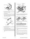
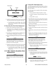
I. Coolant Return Hose (Internal Filter to Flow
Switch) Assembly Replacement
The Coolant Return Hose Assembly goes from the top
outlet of the Internal Filter Assembly to the Flow
Switch Assembly located on the side of the Coolant
Tank. Replace the Hose Assembly using the follow-
ing procedure:
NOTE
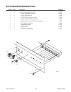
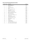
Refer to Subsection 6.05, Front Panel/Chassis Re-
placement Parts for part numbers and detail draw-
ing.
1. Remove the Left Side Panel per Section 5.04-B.
2. Disconnect the Hose Assembly from the outlet side
of the Internal Filter Assembly.
3. Locate the other end of the Hose Assembly at the
lower part of the Flow Switch Assembly.
4. Disconnect the Hose Assembly from the Flow
Switch Assembly.
5. Pull the Hose Assembly from the unit.
6. Install the replacement Hose Assembly by revers-
ing the above procedure.
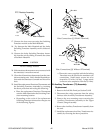
J. Secondary Water/Gas Hose (T-Fitting to T-
Fitting) Assembly Replacement
The Secondary Water/Gas Hose Assembly goes from
the T-Fitting at the Secondary Gas Check Valve to the
T-Fitting on the Secondary Gas Pressure Gauge As-
sembly. Replace the Hose Assembly using the follow-
ing procedure:
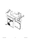
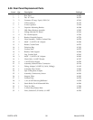
NOTE
Refer to Subsection 6.08, Upper Chassis Replace-
ment Parts for part numbers and detail drawing.
1. Remove the Right Side Panel per Section 5.04-B.
2. Disconnect the Hose Assembly from the T-Fitting
on the Check Valve from the Secondary Gas Regu-
lator Assembly.
3. Disconnect the other end of the Hose Assembly
from the T-Fitting on the Secondary Gas Pressure
Gauge Assembly.
4. Remove the Hose Assembly from the unit.
5. Install the replacement Hose Assembly by revers-
ing the above procedure.
K. Plasma Gas Hose (Plasma Gas Solenoid to
Plasma Gas Regulator) Assembly
Replacement
The Plasma Gas Hose Assembly goes from the Plasma
Gas Solenoid Assembly at the rear panel to the Plasma
Gas Regulator at the front panel. Replace the Hose
Assembly using the following procedure:
NOTE
Refer to Subsection 6.08, Upper Chassis Replace-
ment Parts for part numbers and detail drawing.
1. Remove the Right Side Panel per Section 5.04-B.
2. Disconnect the Hose Assembly from the Plasma
Gas Solenoid Assembly at the rear panel.
3. Disconnect the other end of the Hose Assembly
from the Plasma Gas Regulator Assembly at the
front panel.
4. Remove the Hose Assembly from the unit.
5. Install the replacement Hose Assembly by revers-
ing the above procedure.