


REPLACEMENT PROCEDURES 48 Manual 0-2533
NOTE
Refer to Subsection 6.08, Upper Chassis Replace-
ment Parts for part numbers and detail drawing.
1. Remove the Right Side Panel per Section 5.04-B.
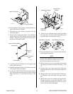
2. Disconnect the Hose Assembly from the T-Fitting
at the front panel Coolant Pressure Gauge connec-
tor.
3. Disconnect the other end of the Hose Assembly
from the Coolant Pressure Gauge.
4. Remove the Hose Assembly from the unit.
5. Install the replacement Hose Assembly by revers-
ing the above procedure.
E. Secondary Gas Hose (T-Fitting to
SECONDARY GAS Connector) Assembly
Replacement
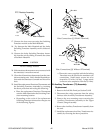
The Secondary Gas Hose Assembly goes from the T-
Fitting to front panel SECONDARY GAS connector.
Replace the Hose Assembly using the following pro-
cedure:
NOTE
Refer to Subsection 6.08, Upper Chassis Replace-
ment Parts for part numbers and detail drawing.
1. Remove the Right Side Panel per Section 5.04-B.
2. Disconnect the Hose Assembly from the T-Fitting
on the Check Valve from the Secondary Gas Regu-
lator Assembly.
3. Disconnect the other end of the Hose Assembly
from the front panel SECONDARY GAS Connec-
tor.
4. Remove the Hose Assembly from the unit.
5. Install the replacement Hose Assembly by revers-
ing the above procedure.
F. Plasma Gas Hose (PLASMA GAS to T-
Fitting) Assembly Replacement
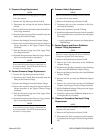
The Plasma Gas Hose Assembly goes from the front
panel PLASMA GAS connector to the T-Fitting on the
Plasma Pressure Gauge Assembly. Replace the Hose
Assembly using the following procedure:
NOTE
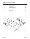
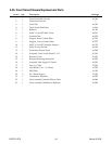
Refer to Subsection 6.08, Upper Chassis Replace-
ment Parts for part numbers and detail drawing.
1. Remove the Right Side Panel per Section 5.04-B.
2. Disconnect the Hose Assembly from the front panel
PLASMA GAS connector.
3. Disconnect the Other end of the Hose Assembly
from the T-Fitting at the Plasma Pressure Gauge
Assembly.
4. Remove the Hose Assembly from the unit.
5. Install the replacement Hose Assembly by revers-
ing the above procedure.
G. Coolant Supply Hose (Coolant Filter to
Pump) Assembly Replacement
The Coolant Supply Hose Assembly goes from the rear
panel Coolant Filter Assembly to the Pump Assem-
bly. Replace the Hose Assembly using the following
procedure:
NOTE
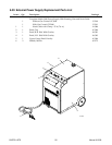
Refer to Subsection 6.07, Base Assembly Replace-
ment Parts for part numbers and detail drawing.
1. Remove the Right Side Panel per Section 5.04-B.
2. Disconnect the Hose Assembly from the Coolant
Filter Assembly on the rear panel.
3. Disconnect the other end of the Hose Assembly
from the Pump Assembly.
4. Remove the Hose Assembly from the unit.
5. Install the replacement Hose Assembly by revers-
ing the above procedure.
H. Coolant Supply Hose (Tank to Coolant
Filter) Assembly Replacement
The Coolant Supply Hose Assembly goes from the
Coolant Tank to the Coolant Filter Assembly mounted
on the rear panel. Replace the Hose Assembly using
the following procedure:
NOTE
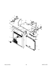
Refer to Subsection 6.06, Rear Panel Replacement
Parts for part numbers and detail drawing.
1. Drain the coolant from the Coolant Tank per Sec-
tion 4.02-F.
CAUTIONS
The coolant must be drained from the unit as the
coolant will drain out the hose connection on the
side of the Coolant Tank .
Handle and dispose of the used coolant per recom-
mended procedures.
2. Disconnect the other end of the Hose Assembly
from the Coolant Tank.