


Manual 0-2533 23 SERVICE TROUBLESHOOTING
U. Main arc transfers and pierces through the plate,
but cutting machine doesn’t move
1. Incorrect or missing OK-To-Move signal.
a. Many cutting machines require an AC voltage
to activate the motion input. Refer to Operat-
ing Manuals for setting OK-To-Move signal.
b. Check for missing OK-To-Move signal. Refer to
Section 4.05-Q, OK-To-Move Tests.
V. Standoff Control Not Working Correctly
Refer to Troubleshooting in the Standoff Control In-
struction Manual.
W. Remote Control Not Working Correctly
Refer to Troubleshooting in the Remote Control In-
struction Manual.
4.05 Test Procedures
The following tests are suggested for specific problems
listed in the troubleshooting guide.
WARNING
Several of these tests involve voltage measurements
that must be made with power on. Use extreme
care when making these tests. Tests requiring volt-
age measurements are marked with the warning
symbol. Disconnect primary power to the system
for all other tests.
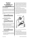
A. Voltage Selection PC Board Check
When wall power is first turned on, the Voltage Se-
lection PC senses the low voltage AC present at J6-20,
J6-22, and J6-24 (center tap). The Voltage Selection
PC Board determines whether the voltage is in the
lower or higher part of the selected input voltage
range. If the input voltage is within the upper part of
the range, the board energizes K1, K4, and K5 relays
(labeled ‘HV’ on the system schematic). If the input
voltage is within the lower part of the range the board
energizes the K2 and K3 relays (labeled ‘LV’ on the
schematic). If HV is selected, the red LED indicator
(D18) on the voltage selection board will be lit. The
relays do not energize until SW1-B (one pole of the
ON/OFF switch) is closed because the DC voltage to
the coils passes through it.
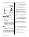
28 VAC Test
1. Check the AC input from J6-24 to both J6-20 and
J6-22 for 12 - 18 VAC.
2. Check the AC voltage from J6-24 to both J6-17 and
J6-18 for 16 - 22 VAC.
3. If input voltages are correct, check output from J6-
24 to both J6-19 and J6-21 for 14 - 18 VAC.
4. If output is not present at J6-19 and J6-21, check
between J6-24 (-) and both J6-16 and J6-23 (+) for
12 - 16 VDC. If voltage is present at both points or
neither, replace the Voltage Selection PC Board. If
voltage is found at J6-23 but not at J6-16, check
SW1-B and all wiring and connections.
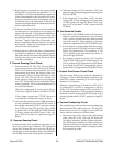
120 VAC Test
NOTE
Refer to Appendix VI for 120 VAC Circuit Dia-
gram.
1. Check the voltage input from F2 (wire #10) to J6-9
for 100 - 120 VAC. Check the input from F2 to J6-
10 for 120 - 140 VAC.
2. If the voltage input is present, check the red LED
indicator (D18) on the voltage selection board. If
the indicator is lit, measure voltage output between
F2 (wire #10) and J6-7. If the indicator is not lit,
measure between F2 and J6-12. The voltage out-
put at either point should measure 110 - 130 VAC.
3. If both or neither J6-7 or J6-12 have high voltage
present, replace the voltage selection board. Check
voltage between J6-21 and wire #10 on fuse F2 for
110 - 130 VAC. This supplies 120 VAC to the rest
of the unit.
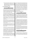
B. Enable Circuit Tests
Relay K1 on the Switching Control PC Board, along
with SW1-A and F2, completes the 120VAC return
path. K1 is energized by the ENABLE switch on the
RC6010 remote or if the remote is not used by a switch
connected to TB1-1 & 2.
Check for K1 being energized by measuring AC volts
from F2 wire #10 to J7-22 and J7-24. It should be 0 v.
If so, refer to Section 4.05-D, Motor Control Contactor
Check (MC1 or MC2), to check motor contactors. If
there is voltage, about 120v, at J7-24 circuit is open
between J7-24 and F2 (F2 or SW1-A open). If there is
no voltage at J7-24 but it is at J7-22 then K1 is not
closed.
If K1 is not closing and the remote is being used tem-
porarily jumper TB2 1 to 2. If the fan and pump come
on the problem is in the remote’s enable circuit. Check
continuity from TB2 back to the remote ENABLE
switch to find the problem. If jumping TB2 did not