


SERVICE TROUBLESHOOTING 30 Manual 0-2533
The display signal at J7-2 should be equal to the
control pot wiper voltage at J7-18 measured in Step
3 above.
If this is not correct, the Switching Control PC
Board is defective.
After arc transfer the display signal switches to
represent actual cutting current as monitored by
the Shunt Amp and Switching Control PC Boards.
At the same time OK-To-Move is sent to the re-
mote shutting off the left hand decimal, refer to
Section 4.05-Q, OK-To-Move Tests. The output of
the Shunt Amp at J9-5 of the Switching Control
PC Board is 5.45 volts for 150 Amps. The display
signal at J7-2 should be 10 volts. If the shunt volt-
age is correct and the display signal is not then
the Switching PC Board is defective.
If the remote display and the shunt amp voltage
at J9-5 is correct but the cutting current is low (mea-
sured with separate ampmeter) then the Shunt
Amp may be faulty but first check step 1 of this
section.
5. Corner Slowdown (CSD)
Corner Slowdown (CSD), a CNC signal, is also
referred to as standoff inhibit or corner current
reduction. The CNC signal comes from the cut-
ting machine controller to inhibit the standoff con-
trol when cutting speed reduction is desired.
Spped reduction may be needed for cutting
around corners where high speeds would ad-
versely affect the standoff regulation. It also can
be used to reduce cutting current when the cut
speed is lowered.
A contact closure between J29-7 and 8 or J6-7 and
8 of the Remote Control (RC 6010) sends an active
low signal to the Standoff Control (SC10) via J5-
21 which turns OFF the Standoff Control THC
ACTIVE indicator, turns ON the three decimals
in the VOLTS display and prevents the Standoff
Control (SC10) from changing torch height.
NOTE
Refer to Appendix XI for Corner Slowdown (CSD)
Circuit Diagram.
At the same time, the CSD relay in the Remote
Control (RC6010) closes switching current control
from the OUTPUT AMPS control to the CSD con-
trol and turning on the three decimals in the AMPS
display. Turning ON switch SW1-1, a dip switch
on the Remote Control PC Board inside the Re-
mote Control (RC6010), will reverse the logic so a
closure is required at the CSD input for normal
operation and an open for CSD.
For the Standoff Control (SC11) used without the
Remote Control (RC6010), the CNC input for CSD
is through J40-10 and J40-11 or J11-1 and J11-2 of
the Standoff Control (SC11). For the Power Sup-
ply, corner current reduction is only available
when using the Remote Control (RC6010). The
CSD relay output at J42 is not used with the Power
Supply.
If the problem is the CSD on all the time or none
of the time disconnect the CSD input from the
cutting machine, set Remote Control (RC6010) in-
ternal switch SW1-1 OFF and jumper the CSD in-
put pins at either J6 or J29 (J42 or J11 for Standoff
Control (SC11). If CSD is on (display indicates
three decimals) when the jumper is connected and
off when the jumper is not connected, the prob-
lem is with the cutting machine or the CNC cable.
If jumping the CSD does not work, the Remote
Control (RC6010) or Standoff Control (SC11) is
faulty. If while using the Remote Control (RC6010)
and Standoff Control (SC10) together, CSD works
in the Remote Control (RC6010) but not the Stand-
off Control (SC10) check for a low, less than 3
VDC., on the ribbon cable at J5-21. If not low, with
CSD on, the Remote Control (RC6010) is faulty. If
J5-21 is low, either the Standoff Control (SC10) is
faulty or the ribbon cable is open.
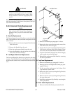
P. 48 Volt Bias Test
1. Remove the remote cable from the Remote Control
(RC6010), or the Standoff Control (SC11). Tempo-
rally jumper TB2-1 to TB2-2 for enable.
For the Remote Control (RC 6010), measure for
+48 +/-5 VDC from J37-16, 35 and 37 (+) to J37-
15,34 and 36 (-). If correct, Remote Control RC6010
is faulty.
For the Standoff Control (SC11), measure J41-3 and
4 (+) to J41-1 and 2 (-). If correct, Standoff Control
(SC11) is faulty.
2. If the 48 VDC is not correct, go the Power Supply
and measure for +48 +/- 5 VDC at J31-1 to 2 of the
Bias PC Board. If correct, check for open in the
Power Supply harness to J15 or the remote cable.
If 48 VDC is not correct, remove J31 from the Bias
PC Board as and measure again (on the Bias PC
Board). If correct, check for a short in the wiring
harness of remote cable.
3. If 48 VDC is still incorrect check for 115 VAC at J30-
1 to J30-3 at the Bias PC Board. If correct, replace
Bias PC Board. Also, check Fuse (F1), 3A 250v, on
the Bias PC Board.