


Manual 0-2533 33 REPLACEMENT PROCEDURES
SECTION 5:
REPAIRS & REPLACEMENT
PROCEDURES
5.01 Introduction
This Section describes parts replacement procedures and
all repairs which may be performed on the Merlin 3000
Power Supply.
Under no circumstances are field repairs to be attemped
on Printed Circuit Boards or other Subassemblies of this
unit. Evidence of unauthorized repairs may void the fac-
tory warranty.
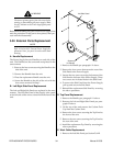
5.02 Anti-Static Handling
Procedures
A. General
CAUTION
PC boards can be irreparably damaged by improper
handling due to electrostatic discharge (ESD).
Replacement PC boards are shipped in a protective en-
closure to prevent damage from electrostatic discharge
(ESD) during shipping. Included with each replacement
board is a ground strap to prevent static damage during
installation.
WARNINGS
Read and understand these instructions and the
instructions on the grounding wrist strap package
before opening the equipment enclosure or remov-
ing the replacement PC board from its protective
enclosure.
Disconnect primary power to the system before dis-
assembling the torch, torch leads, or power supply
enclosure.
Do not operate the equipment or test equipment
under power while wearing the grounding wrist
strap.
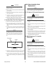
B. Procedure
1. Open the wrist strap and unwrap the first two folds
of the band. Wrap the adhesive side firmly around
your wrist.
2. Unroll the rest of the band and peel the liner from
the copper foil at the opposite end.
3. Attach the copper foil to a convenient and exposed
electrical ground.
4. Connect the equipment primary cable ground to
the same electrical ground as the wrist strap.
5. Open the equipment enclosure (see instruction
manual for the appropriate equipment) and re-
move the failed PC board.
6. Carefully open the ESD protective bag and remove
the replacement PC board.
7. Install the replacement PC board in the equipment
and make all necessary connections.
8. Place the failed PC board in the ESD protective bag
and seal for return shipping.
9. Reassemble the equipment enclosure (see instruc-
tion manual for the appropriate equipment).
10. Remove the grounding wrist strap from your wrist
and from the electrical ground connection before
reconnecting primary power to the equipment.
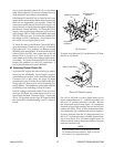
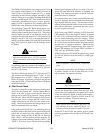
5.03 Parts Replacement - General
Information
The parts replacement procedures described in this
manual, except for Rear Panel Coolant Filter and exter-
nal Fuse(s) replacement, require that the Power Supply
be disassembled. Depending on the part to be replaced
will determine to what extent the Power Supply must be
disassembled.
NOTES
Before removing any electrical connection mark
each wire with the connection designation. When
reassembling this makes sure the wires go to the
proper terminals.
Note the routing of wires and make sure the wires
are put back in the same place when reassembling
the unit.
Turn OFF all gas inputs to the Power Supply at
the source before diconnecting any gas Hose As-
semblies.
Each Subsection is referenced to Section 6 for parts lists
and overall detailed drawing.