


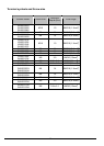
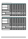
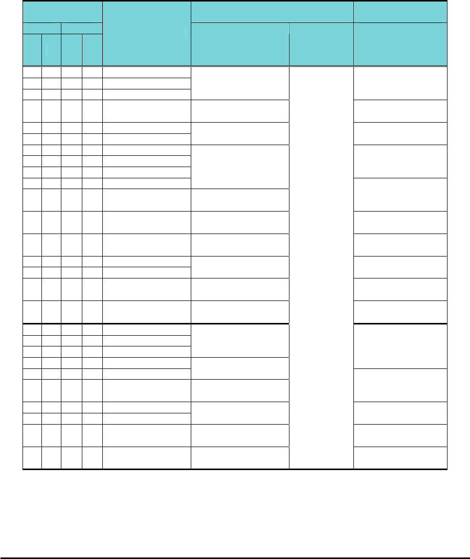
10
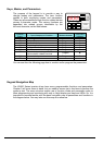
Determining Wire and Fuse Sizes
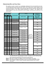
The maximum motor currents in your application determines the recommended wore size.
The following table gives the wire size in AWG. The “Power Lines” column applies to the
inverter input power, output wires to the motor, the earth ground connection, and any other
components shown in the “Basic System Description” on page 9. The “Signal Lines”
column applies to any wire connecting to the two green connectors just inside the front
cover panel.
Motor Output Wiring
Applicable
equipment
kW HP
VT CT VT CT
Inverter Model
Power Lines Signal Lines
Fuse (UL-rated,
class J, 600V ,
Maximum
allowable current)
0.2 0.1 ¼ 1/8
WJ200-001SF
0.4 0.2 ½ ¼
WJ200-002SF
0.55
0.4 ¾ ½
WJ200-004SF
AWG16 / 1.3mm
2
(75°C only)
10A
1.1
0.75
1.5 1
WJ200-007SF
AWG12 / 3.3mm
2
(75°C only)
20A
2.2 1.5 3 2
WJ200-015SF
3.0 2.2 4 3
WJ200-022SF
AWG10 / 5.3mm
2
30A
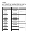
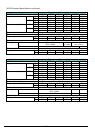
0.2 0.1 ¼ 1/8
WJ200-001LF
0.4 0.2 ½ ¼
WJ200-002LF
0.75
0.4 1 ½
WJ200-004LF
10A
1.1
0.75
1.5 1
WJ200-007LF
AWG16 / 1.3mm
2
2.2 1.5 3 2
WJ200-015LF
AWG14 / 2.1mm
2
(75°C only)
15A
3.0 2.2 4 3
WJ200-022LF
AWG12 / 3.3mm
2
(75°C only)
20A
5.5 3.7 7.5 5
WJ200-037LF
AWG10 / 5.3mm
2
(75°C only)
30A
7.5 5.5 10 7.5
WJ200-055LF
11 7.5 15 10
WJ200-075LF
AWG6 / 13mm
2
(75°C only)
60A
15 11 20 15
WJ200-110LF
AWG4 / 21mm
2
(75°C only)
80A
18.5
15 25 20
WJ200-150LF
AWG2 / 34mm
2
(75°C only)
80A
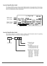
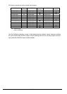
0.75
0.4 1 ½
WJ200-004HF
1.5
0.75
2 1
WJ200-007HF
2.2 1.5 3 2
WJ200-015HF
AWG16 / 1.3mm
2
3.0 2.2 4 3
WJ200-022HF
10A
4.0 3.0 5 4
WJ200-030HF
AWG14 / 2.1mm
2
5.5 4.0 7.5 5
WJ200-040HF
AWG12 / 3.3mm
2
(75°C only)
15A
7.5 5.5 10 7.5
WJ200-055HF
11 7.5 15 10
WJ200-075HF
AWG10/ 5.3mm
2
(75°C only)
30A
15 11 20 15
WJ200-110HF
AWG6 / 13mm
2
(75°C only)
50A
18.5
15 25 20
WJ200-150HF
AWG6 / 13mm
2
(75°C only)
18 to 28
AWG / 0.14
to 0.75 mm
2
shielded wire
(see Note 4)
50A
Note 1: Field wiring must be made by a UL-Listed and CSA-certified closed-loop terminal
connector sized for the wire gauge involved. Connector must be fixed by using
the crimping tool specified by the connector manufacturer.
Note 2: Be sure to consider the capacity of the circuit breaker to be used.
Note 3: Be sure to use a larger wire gauge if power line length exceeds 66ft. (20m).
Note 4: Use 18 AWG / 0.75mm
2
wire for the alarm signal wire ([AL0], [AL1], [AL2]
terminals).