


22
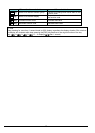
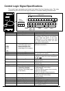
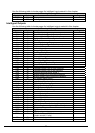
Terminal Name Description Ratings
O Analog voltage input 0 to 9.8 VDC range, 10 VDC nominal,
input impedance 10 kΩ
H +10V analog reference 10VDC nominal, 10mA max.
SP, SN Serial communication terminal For RS485 Modbus communication.
AL0, AL1, AL2 *3 Relay common contact 250VAC, 2.5A (R load) max.
250VAC, 0.2A (I load, P.F.=0.4) max.
100VAC, 10mA min.
30VDC, 3.0A (R load) max.
30VDC, 0.7A (I load, P.F.=0.4) max.
5VDC, 100mA min.
Note 1: The two terminals [L] are electrically connected together inside the inverter.
Note 2: We recommend using [L] logic GND (to the right) for logic input circuits and [L]
analog GND (to the left) for analog I/O circuits.
Note 3: Refer to page 39 for details of trip signals.
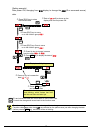
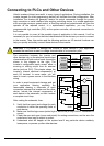
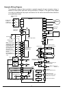
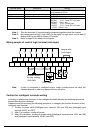
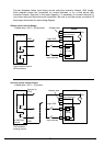
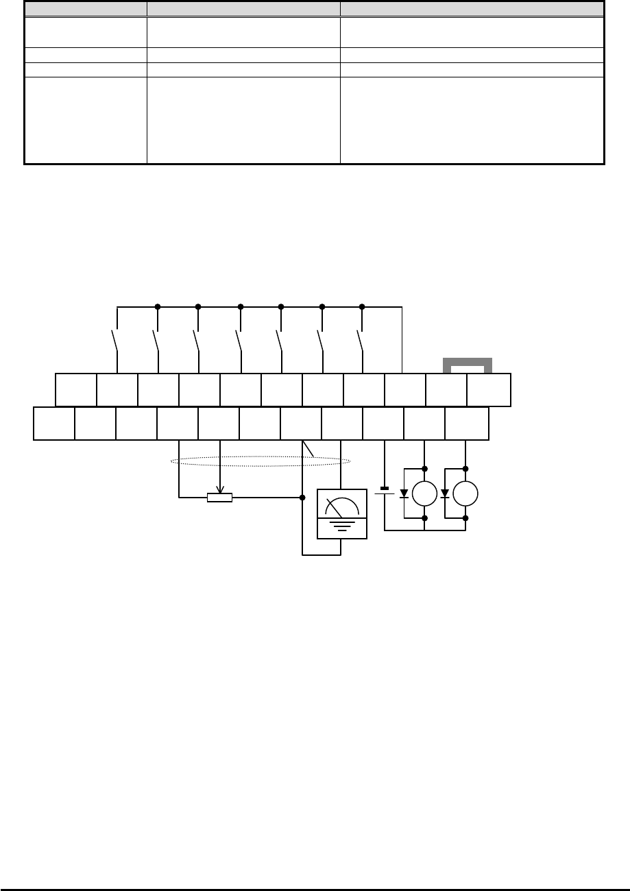
Wiring sample of control logic terminal (sink logic)
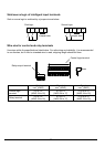
Note: If relay is connected to intelligent output, install a diode across the relay coil
(reverse-biased) in order to suppress the turn-off spike.
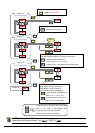
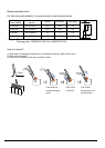
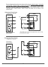
Caution for intelligent terminals setting
In turning on power when the input to the intelligent terminals become the following operations,
the set data might be initialized.
Please ensure not becoming the following operations, in changing the function allocation of the
intelligent input terminal.
1) Turning on power while [Intelligent input terminal 1/2/3 are ON] and [Intelligent input
terminal 4/5/6/7 are OFF].
2) After 1)'s condition, turning off power.
3) After 2)'s condition, turning on power while [Intelligent input terminal 2/3/4 are ON]
and [Intelligent input terminal 1/5/6/7 are OFF].
SP EO EA H O OI L AM
CM2
12 11/EDM
Freq. meter
Variable resistor
for freq. setting
(
1k
Ω
-2kΩ
)
Jumper wire
(sink logic)
RY
SN 7/EB 6 5/PTC
4/GS2
3/GS1
2
1 L PLC
P24
RY