


39
Alarm Signal
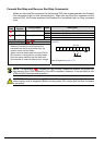
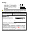
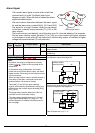
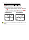
The inverter alarm signal is active when a fault has
occurred and it is in the Trip Mode (refer to the
diagram at right). When the fault is cleared the alarm
signal becomes inactive.
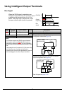
We must make a distinction between the alarm signal
AL and the alarm relay contacts [AL0], [AL1] and [AL2].
The signal AL is a logic function, which you can assign
to the open collector output terminals [11], [12], or the
relay outputs.
The most common (and default) use of the relay is for AL, thus the labeling of its terminals.
Use an open collector output (terminal [11] or [12]) for a low-current logic signal interface
or to energize a small relay (50 mA maximum). Use the relay output to interface to higher
voltage and current devices (10 mA minimum).
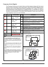
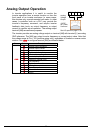
Option
Code
Terminal
Symbol
Function Name State Description
ON when an alarm signal has occurred and has not
been cleared
05
AL Alarm Signal
OFF when no alarm has occurred since the last clearing
of alarm(s)
Valid for inputs:
11, 12, AL0 – AL2
Required settings
C031, C032, C036
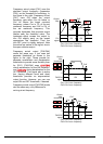
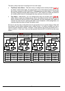
Notes:
• By default, the relay is configured as normally
closed (C036=01). Refer to the next page for an
explanation.
• In the default relay configuration, an inverter
power loss turns ON the alarm output. the alarm
signal remains ON as long as the external control
circuit has power.
• When the relay output is set to normally closed, a
time delay of less than 2 seconds occurs after
powerup before the contact is closed.
• Terminals [11] and [12] are open collector
outputs, so the electric specifications of [AL] are
different from the contact output terminals [AL0],
[AL1], [AL2].
• This signal output has the delay time (300 ms
nominal) from the fault alarm output.
• The relay contact specifications are in “Control
Logic Signal Specifications” on page 4–6. The
contact diagrams for different conditions are on
the next page.
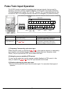
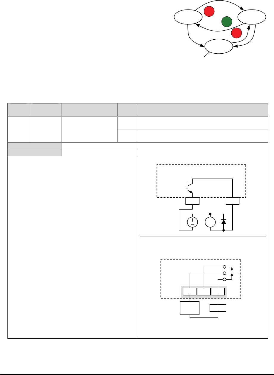
Example for terminal [11] (default output
configuration shown see page 66):
Example for terminal [AL0], [AL1], [AL2] (requires
output configuration see page 66):
See I/O specs on page 21,22.
Run Stop
RUN
STOP
RESET
Trip
STOP
RESET
Fault
Fault
A
larm signal active
RY
Inverter output
terminal circuit
CM2 11
A
L
AL1
Power
supply
Load
AL0 AL2
Inverter logic
circuit board
A
L