


29
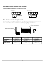
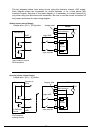
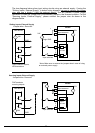
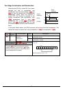
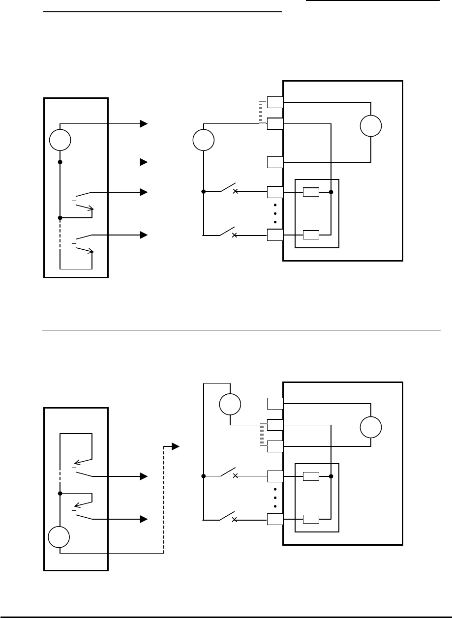
The two diagrams below show input wiring circuits using an external supply. If using the
“Sinking Inputs, External Supply” in below wiring diagram, be sure to remove the jumper
wire, and use a diode (*) with the external supply. This will prevent a power supply
contention in case the jumper wire is accidentally placed in the incorrect position. For the
“Sourcing Inputs, External Supply”, please connect the jumper wire as drawn in the
diagram below.
Sinking Inputs, External Supply
Jumper wire = Removed
GND
7
1
Field device
Open collector outputs,
NPN transistors
WJ200
P24
1
7
24V
PLC
Input
circuits
+
-
Logic GND
Input common
Input switches
L
24V
+
-
+
-
24V
*
* Note: Make sure to remove the jumper wire in case of using
an external power supply.
Sourcing Inputs, External Supply
Jumper wire = Removed
7
1
Field device
WJ200
P24
1
7
24V
PLC
Input
circuits
+
-
Input common
Input switches
L
GND
PNP transistor
sourcing outputs
24V
+
-
24V
+
-