


97
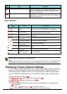
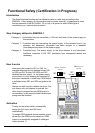
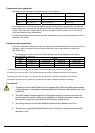
Components to be combined
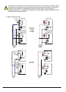
Followings are the example of the safety devices to be combined.
Series Model Norms to comply Certification date
GS9A 301 ISO13849-2 cat4, SIL3 06.06.2007
G9SX GS226-T15-RC IEC61508 SIL1-3 04.11.2004
NE1A SCPU01-V1 IEC61508 SIL3 27.09.2006
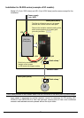
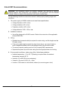
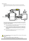
The configuration of and components used in any circuit other than an appropriately pre approved
safety module that interfaces with the WJ200 GS1/GS2 and EDM ports MUST be at least equivalent
to CAT 3 PLd under ISO 13849-1:2006 in order to be able to claim an overall CAT 3 PLd for the
WJ200 and external circuit combination.
The EMI level that the external module has been assessed to must be at least equivalent to that of
Appendix E IEC 62061.
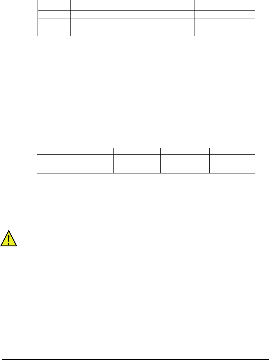
Periodical check (proof test)
Proof test is essential to be able to reveal any dangerous undetected failures after a period of time, in
this case 1 year. Carrying out this proof test at least one a year is the condition to comply the
ISO13849-1 PLd.
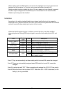
- To activate (give current to) GS1 and GS2 simultaneously and separately to see output is
allowed and EDM is conducting
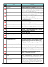
Terminal Status
GS1 current OFF current ON current OFF current ON
GS2 current OFF current OFF current ON current ON
EDM conducted not conducted Not conducted not conducted
(output) forbidden forbidden forbidden Allowed
- To activate (give current to) both GS1 and GS2 to see output is allowed and EDM is not conducting
- To activate (give current to) GS1, not to activate GS2 and see output is forbidden and EDM is not conducting
- To activate (give current to) GS2, not to activate GS1 and see output is forbidden and EDM is not conducting
- To deactivate (interrupt current to) both GS1 and GS2 to see output is forbidden and EDM is conducting
Precautions
1. To assure, that the Safe Disable function appropriately fulfills the safety requirements
of the application, a throughout risk assessment for the whole safety system has to be
carried out.
2. The Safe Disable function does not cut the power supply to the drive and does not
provide electrical isolation. Before any installation or maintenance work is done, the
drives power supply must be switched off and place a tag/lock-out.
3. The wiring distance for the Safe Disable inputs should be shorter than 30 m.
4. The time from opening the Safe Disable input until the drive output is switched off is
less than 10 ms.