


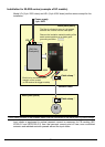
95
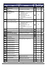
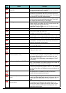
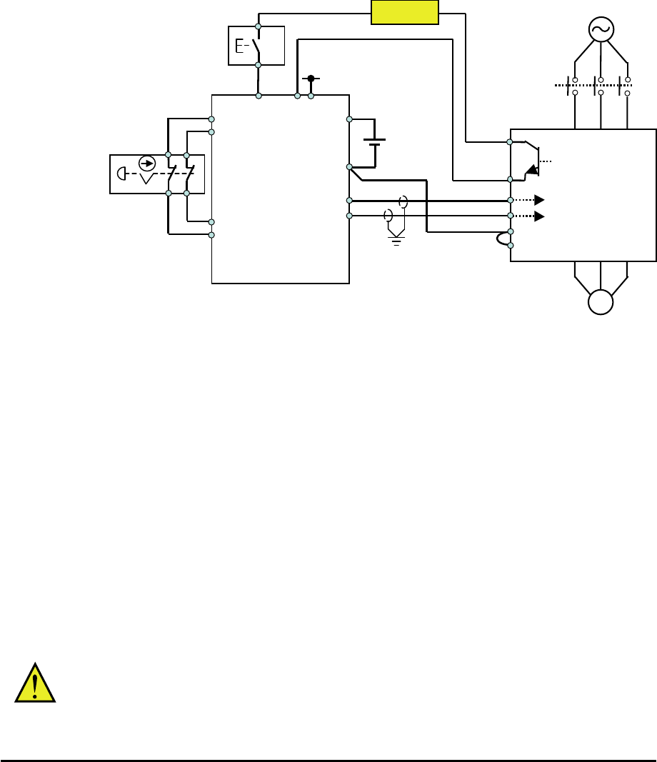
Wiring example
When the Gate Suppress function is utilized, connect the drive to a safety certified
interrupting device utilizing EDM output signal to reconfirm both safety inputs GS1 and
GS2.
By pressing the emergency stop button, the current to GS1 and GS2 is shut off, and the
inverter output is shut off. By this, motor is free-running. This behavior is according to the
stop category 0 defined in EN60204.
Note 1: Above is the example to use the intelligent input terminal with source logic. When
it is used with sink logic, the wiring is to be modified.
Note 2: The wire for safety relay and emergency input signal are to be shielded coaxial
cable for example RS174/U (produced by LAPP) by MIL-C17, or KX2B by NF C
93-550 with diameter 2.9mm with less than 2 meters. Please be sure to ground
the shielding.
Note 3: All the inductance related parts such as relay and contactor are required to
contain the over-voltage protection circuit.
The arch extinguishing fuse with rated voltage AC250V, rated current 100mA complies
to either IEC6127 –2/-3/-4
Example)
SOC EQ series AC250V, 100mA (UL, SEMKO, BSI)
Little 216 series AC250V, 100mA (CCC, UL, CSA, SEMKO, CE, VDE)
EDM
(feedback) input
WJ200
Safety output
Safety Unit
※Standard
(IEC61508,ISO13849)
certified
KM1
M
Reset
Switch
GS2
GS1
EDM
CM2
Safety input
S14
S24
T12
T21
T22
A1
A
2
Safety Switch
(Example: emergency
push button)
T11
T31
T32
PLC
L
+24V
T33
+24V
Fuse
G9SX-GS226-T15-RC