


27
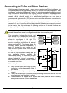
Using Intelligent Input Terminals
Terminals [1], [2], [3], [4], [5], [6] and [7] are identical, programmable inputs for general use.
The input circuits can use the inverter’s internal (isolated) +24V field supply or an external
power supply. This section describes input circuits operation and how to connect them
properly to switches or transistor outputs on field devices.
The WJ200 inverter features selectable sinking or sourcing inputs. These terms refer to the
connection to the external switching device–it either sinks current (from the input to GND)
or sources current (from a power source) into the input. Note that the sink/source naming
convention may be different in your particular country or industry. In any case, just follow
the wiring diagrams in this section for your application.
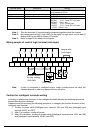
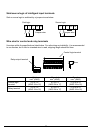
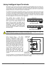
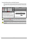
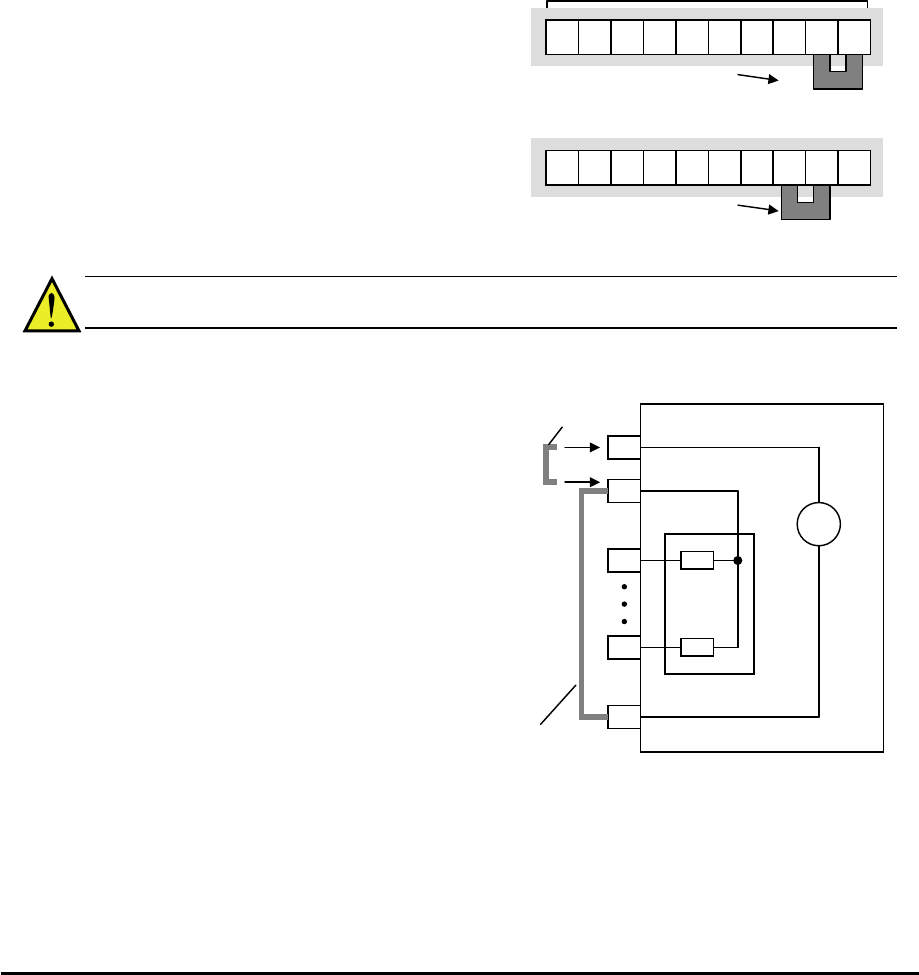
The inverter has a jumper wire for
configuring the choice of sinking or sourcing
inputs. To access it, you must remove the
front cover of the inverter housing. In the
figure to the top right, the jumper wire is
shown as attached to the logic terminal block
(connector). If you need to change to the
source type connection, remove the
jumper
wire and connect it as shown in the figure at
the bottom right.
CAUTION: Be sure to turn OFF power to the inverter before changing the
jumper wire
position. Otherwise, damage to the inverter circuitry may occur.
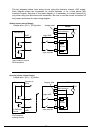
[PLC] Terminal Wiring – The [PLC]
terminal (Programmable Logic Control
terminal) is named to include various
devices that can connect to the inverter’s
logic inputs. In the figure to the right, note
the [PLC] terminal and the jumper wire.
Locating the jumper wire between [PLC]
and [L] sets the input logic source type,
which is the default setting for EU and
US versions. In this case, you connect
input terminal to [P24] to make it active. If
instead you locate the jumper wire
between [PLC] and [P24], the input logic
will be sink type. In this case, you
connect the input terminal to [L] to make
it active.
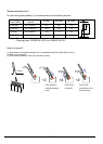
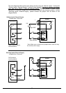
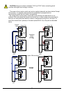
The wiring diagram on the following pages show the four combinations of using sourcing or
sinking inputs, and using the internal or an external DC supply.
WJ200 inverter
P24
1
7
L
24V
PLC
Input
circuits
+
-
Logic GND
Input common
Jumper wire
for sink lo
g
ic
Jumper wire
for source lo
g
ic
Lo
g
ic in
p
uts
5 4 3 2 1 L
PLC
P24
Source lo
g
ic connection
Jum
p
er wire
7 6
5 4 3 2 1 L
PLC
P24
Sink lo
g
ic connection
Jumper wire
7 6