


72
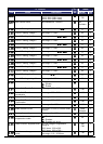
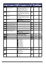
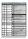
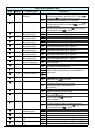
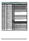
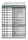
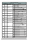
Input Function Summary Table
Option
Code
Terminal
Symbol
Function Name Description
ON
Frequency output uses 2nd-stage acceleration and
deceleration values
09
2CH
2-stage Acceleration
and Deceleration
OFF
Frequency output uses standard acceleration and
deceleration values
ON
Causes output to turn OFF, allowing motor to free run
(coast) to stop
11
FRS Free-run Stop
OFF
Output operates normally, so controlled deceleration
stop motor
ON
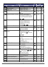
When assigned input transitions OFF to ON, inverter
latches trip event and displays
E 12
12
EXT External Trip
OFF
No trip event for ON to OFF, any recorded trip events
remain in history until reset
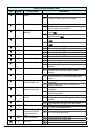
ON
On powerup, the inverter will not resume a Run
command (mostly used in the US)
13
USP
Unattended Start
Protection
OFF
On powerup, the inverter will resume a Run command
that was active before power loss
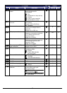
ON Motor can be driven by commercial power
14
CS
Commercial power
source switchover
OFF Motor is driven via the inverter
ON
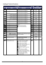
The keypad and remote programming devices are
prevented from changing parameters
15
SFT Software Lock
OFF The parameters may be edited and stored
ON
16
AT
Analog Input
Voltage/Current Select
OFF
Refer to “Analog Input Operation” on page 41.
ON
The trip condition is reset, the motor output is turned
OFF, and powerup reset is asserted
18
RS Reset Inverter
OFF Normal power-ON operation
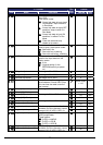
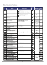
ANLG
When a thermistor is connected to terminal [5] and [L],
the inverter checks for over-temperature and will cause
trip event and turn OFF output to motor
19
PTC
PTC thermistor
Thermal Protection
(C005 only)
OPEN
A disconnect of the thermistor causes a trip event, and
the inverter turns OFF the motor
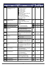
ON Starts the motor rotation
20
STA Start
(3-wire interface)
OFF
No change to present motor status
ON Stops the motor rotation
21
STP Stop
(3-wire interface)
OFF No change to present motor status
ON Selects the direction of motor rotation: ON = FWD.
While the motor is rotating, a change of F/R will start a
deceleration, followed by a change in direction
22
F/R FWD, REV
(3-wire interface)
OFF Selects the direction of motor rotation: OFF = REV.
While the motor is rotating, a change of F/R will start a
deceleration, followed by a change in direction
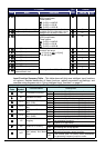
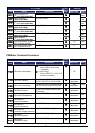
ON Temporarily disables PID loop control. Inverter output
turns OFF as long as PID Enable is active (A071=01)
23
PID PID Disable
OFF Has no effect on PID loop operation, which operates
normally if PID Enable is active (A071=01)
ON Resets the PID loop controller. The main consequence
is that the integrator sum is forced to zero
24
PIDC PID Reset
OFF No effect on PID controller
ON Accelerates (increases output frequency) motor from
current frequency
27
UP Remote Control UP
Function (motorized
speed pot.)
OFF Output to motor operates normally
ON Decelerates (decreases output frequency) motor from
current frequency
28
DWN Remote Control Down
Function (motorized
speed pot.)
OFF Output to motor operates normally