


50
Standard Functions
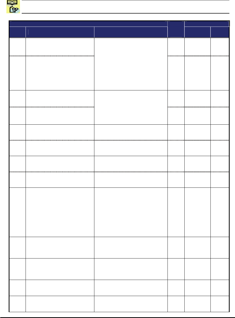
NOTE:. Mark “” in b031=10 shows the accessible parameters when b031 is set “10”, high
level access.
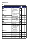
“A” Function Defaults
Func.
Code
Name Description
Run
Mode
Edit
Initial data Units
A001
Frequency source
U
02
−
A201
Frequency source,
2
nd
motor
Eight options; select codes:
00 …POT on ext. operator
01 …Control terminal
02 …Function F001 setting
03 …Modbus network input
04 …Option
06 …Pulse train input
07 …via EzSQ
10 …Calculate function output
U
02
−
A002
Run command source
U
02
−
A202
Run command source,
2
nd
motor
Four options; select codes:
01 …Control terminal
02 …Run key on keypad, or
digital operator
03 …Modbus network input
04 …Option
U
02
−
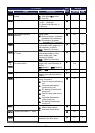
A003
Base frequency Settable from 30 Hz to the
maximum frequency(A004)
U
60.0 Hz
A203
Base frequency,
2
nd
motor
Settable from 30 Hz to the 2
nd
maximum frequency(A204)
U
60.0 Hz
A004
Maximum frequency Settable from the base
frequency to 400 Hz
U
60.0 Hz
A204
Maximum frequency,
2
nd
motor
Settable from the 2
nd
base
frequency to 400 Hz
U
60.0 Hz
A005
[AT] selection Three options; select codes:
00...Select between [O] and [OI]
at [AT] (ON=OI, OFF=O)
02...Select between [O] and
external POT at [AT]
(ON=POT, OFF=O)
03...Select between [OI] and
external POT at [AT]
(ON=POT, OFF=OI)
U
00
−
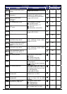
A011
[O] input active range start
frequency
The output frequency
corresponding to the analog
input range starting point,
range is 0.00 to 400.0
U
0.00 Hz
A012
[O] input active range end
frequency
The output frequency
corresponding to the analog
input range ending point,
range is 0.0 to 400.0
U
0.00 Hz
A013
[O] input active range start
voltage
The starting point (offset) for the
active analog input range,
range is 0. to 100.
U
0. %
A014
[O] input active range end
voltage
The ending point (offset) for the
active analog input range,
range is 0. to 100.
U
100. %