


71
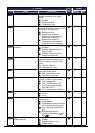
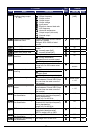
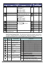
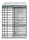
“C” Function Defaults
Func.
Code
Name Description
Run
Mode
Edit
Initial data Units
C147
Logic output 2 operator Applies a logic function to calculate
[LOG] output state,
Three options:
00…[LOG] = A AND B
01…[LOG] = A OR B
02…[LOG] = A XOR B
U
00
−
C148
Logic output 3 operand A
U
00
−
C149
Logic output 3 operand B
All the programmable functions
available for logic (discrete) outputs
except LOG1 to LOG3, OPO, no
U
01
−
C150
Logic output 3 operator Applies a logic function to calculate
[LOG] output state,
Three options:
00…[LOG] = A AND B
01…[LOG] = A OR B
02…[LOG] = A XOR B
U
00
−
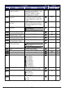
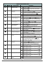
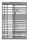
C160
Input [1] response time
U
1.
−
C161
Input [2] response time
U
1.
−
C162
Input [3] response time
U
1.
−
C163
Input [4] response time
U
1.
−
C164
Input [5] response time
U
1.
−
C165
Input [6] response time
U
1.
−
C166
Input [7] response time
Sets response time of each input
terminal, set range:
0 (x 2 [ms]) to 200 (x 2 [ms])
(0 to 400 [ms])
U
1.
−
C169
Multistage speed/position
determination time
Set range is 0. to 200. (x 10ms)
U
0. ms
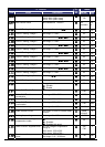
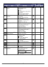
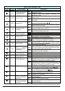
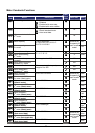
Input Function Summary Table – This table shows all thirty-one intelligent input functions
at a glance. Detailed description of these functions, related parameters and settings, and
example wiring diagrams are in “Using Intelligent Input Terminals” on page 27.
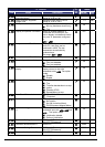
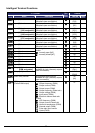
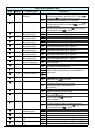
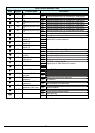
Input Function Summary Table
Option
Code
Terminal
Symbol
Function Name Description
ON Inverter is in Run Mode, motor runs forward
00
FW FORWARD Run/Stop
OFF Inverter is in Stop Mode, motor stops
ON Inverter is in Run Mode, motor runs reverse
01
RV Reverse Run/Stop
OFF Inverter is in Stop Mode, motor stops
ON Binary encoded speed select, Bit 0, logical 1
02
CF1
Multi-speed Select,
Bit 0 (LSB)
OFF Binary encoded speed select, Bit 0, logical 0
ON Binary encoded speed select, Bit 1, logical 1
03
CF2
Multi-speed Select,
Bit 1
OFF Binary encoded speed select, Bit 1, logical 0
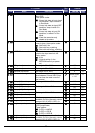
ON Binary encoded speed select, Bit 2, logical 1
04
CF3
Multi-speed Select,
Bit 2
OFF Binary encoded speed select, Bit 2, logical 0
ON Binary encoded speed select, Bit 3, logical 1
05
CF4
Multi-speed Select,
Bit 3 (MSB)
OFF Binary encoded speed select, Bit 3, logical 0
ON
Inverter is in Run Mode, output to motor runs at
jog parameter frequency
06
JG Jogging
OFF Inverter is in Stop Mode
ON DC braking will be applied during deceleration
07
DB External DC braking
OFF DC braking will not be applied
ON
The inverter uses 2nd motor parameters for
generating frequency output to motor
08
SET
Set (select) 2nd Motor
Data
OFF
The inverter uses 1st (main) motor parameters
for generating frequency output to motor