


15
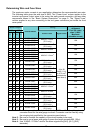
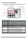
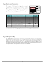
Keys, Modes, and Parameters
The purpose of the keypad is to provide a way to
change modes and parameters. The term function
applies to both monitoring modes and parameters.
These are all accessible through function codes that are
primary 4-character codes. The various functions are
separated into related groups identifiable by the
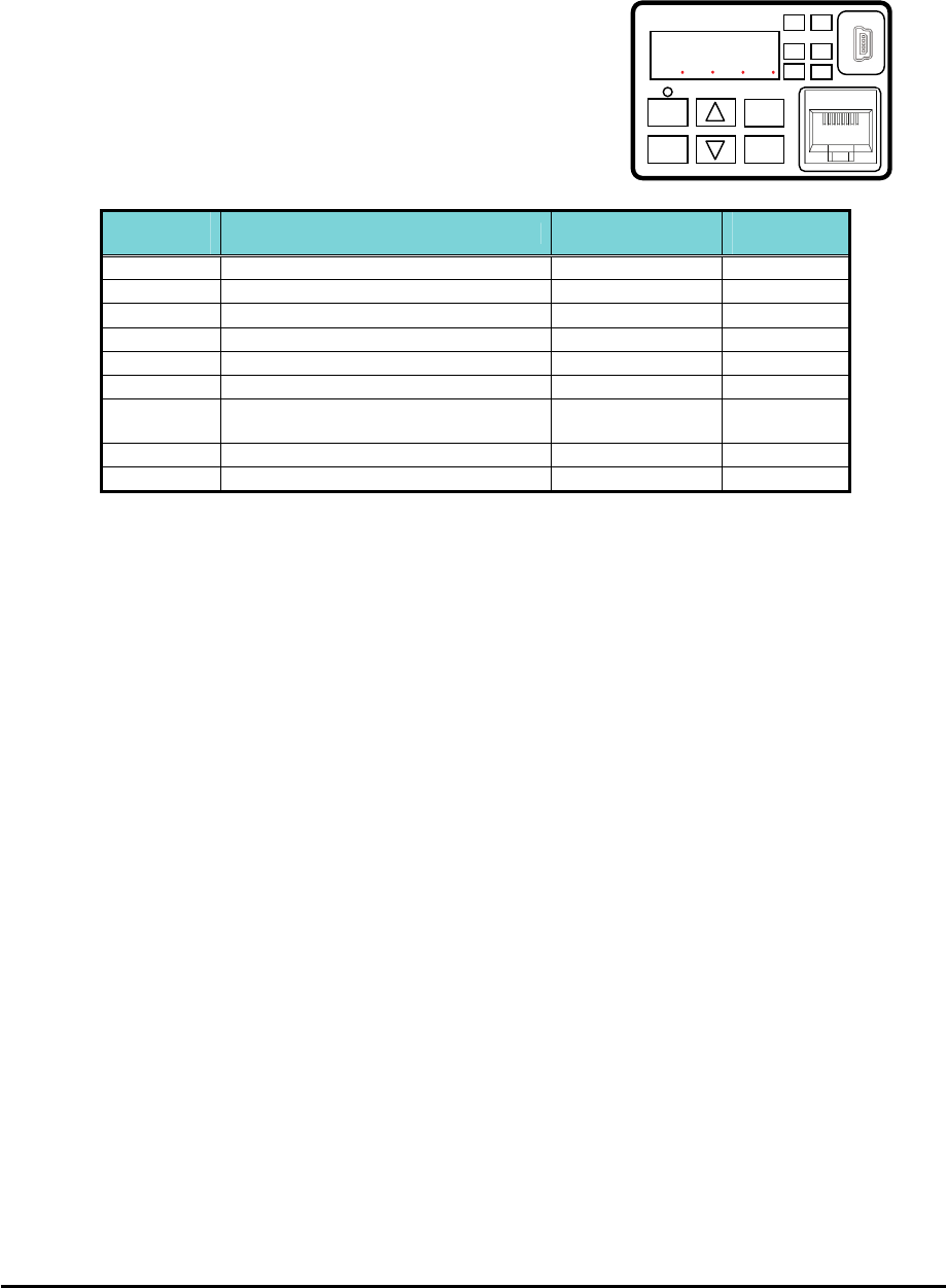
left-most character, as the table shows.
Function
Group
Type (Category) of Function Mode to Access
PRG LED
Indicator
“d” Monitoring functions Monitor
“F” Main profile parameters
Program
“A” Standard functions
Program
“b” Fine tuning functions
Program
“C” Intelligent terminal functions
Program
“H” Motor constant related functions
Program
“P” Pulse train input, torque, EzSQ, and
communication related functions
Program
“U” User selected parameters
Program
“E” Error codes
− −
You can see from the following page how to monitor and/or program the parameters.
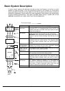
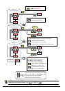
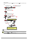
Keypad Navigation Map
The WJ200 Series inverter drives have many programmable functions and parameters.
Chapter 3 will cover these in detail, but you need to access just a few items to perform the
powerup test. The menu structure makes use of function codes and parameter codes to
allow programming and monitoring with only a 4-digit display and keys and LEDs. So, it is
important to become familiar with the basic navigation map of parameters and functions in
the diagram below. You may later use this map as a reference.
8888
RUN
RUN
ESC
SET
STOP
RESET
1
2
PWR
Hz
ALM
PGM
A