


69
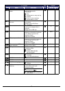
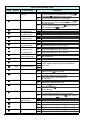
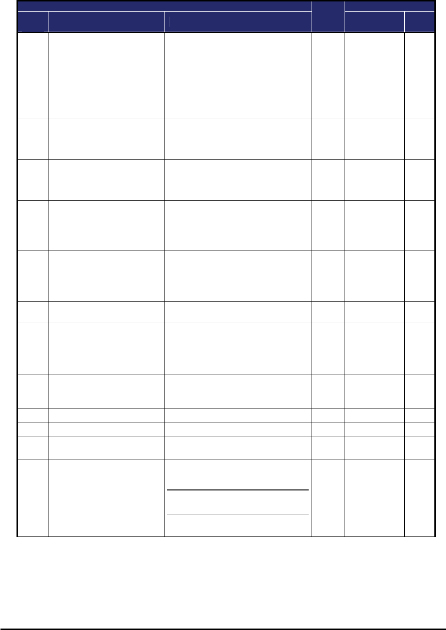
“C” Function Defaults
Func.
Code
Name Description
Run
Mode
Edit
Initial data Units
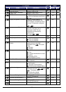
C076
Communication error
select
Selects inverter response to
communications error.
Five options:
00…Trip
01…Decelerate to a stop and trip
02…Disable
03…Free run stop (coasting)
04…Decelerates to a stop
U
02
−
C077
Communication error
time-out
Sets the communications watchdog
timer period.
Range is 0.00 to 99.99 sec
0.0 = disabled
U
0.00 sec.
C078
Communication wait time Time the inverter waits after
receiving a message before it
transmits.
Range is 0. to 1000. ms
U
0. msec.
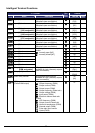
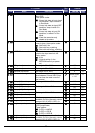
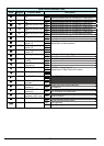
C081
O input span calibration Scale factor between the external
frequency command on terminals
L–O (voltage input) and the
frequency output,
range is 0.0 to 200%
100.0 %
C082
OI input span calibration Scale factor between the external
frequency command on terminals
L–OI (voltage input) and the
frequency output,
range is 0.0 to 200%
100.0 %
C085
Thermistor input (PTC)
span calibration
Scale factor of PTC input.
Range is 0.0 to 200%
100.0 %
C091
Debug mode enable Displays debug parameters.
Two option codes:
00…Disable
01…Enable <Do not set>
(for factory use)
00
−
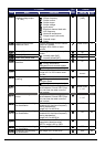
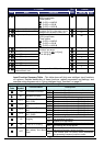
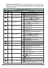
C096
Communication selection
00…Modbus-RTU
01… EzCOM
02… EzCOM<administrator>
U
00
−
C098
EzCOM start adr. of master 01-08
U
01
−
C099
EzCOM end adr. of master 01-08
U
01
−
C100
EzCOM starting trigger
00… Input terminal
01… Always
U
00
−
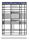
C101
Up/Down memory mode
selection
Controls speed setpoint for the
inverter after power cycle.
Two option codes:
00…Clear last frequency (return to
default frequency F001)
01…Keep last frequency adjusted
by UP/DWN
U
00
−