


70
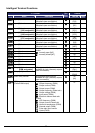
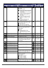
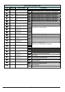
“C” Function Defaults
Func.
Code
Name Description
Run
Mode
Edit
Initial data Units
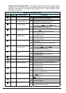
C102
Reset selection Determines response to Reset
input [RS].
Four option codes:
00…Cancel trip state at input signal
ON transition, stops inverter if
in Run Mode
01…Cancel trip state at signal OFF
transition, stops inverter if in
Run Mode
02…Cancel trip state at input ON
transition, no effect if in Run
Mode
03…Clear the memories only
related to trip status
U
00
−
C103
Restart mode after reset Determines the restart mode after
reset is given, three option codes:
00…Start with 0 Hz
01…Start with freq. matching
02…Start with active freq. matching
U
00 -
C104
UP/DWN clear mode Freq. set value when UDC signal is
given to the input terminal, two
option codes:
00…0 Hz
01…Original setting (in the
EEPROM memory at power
on)
U
00 -
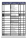
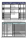
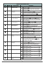
C105
EO gain adjustment Set range is 50 to 200%
100. %
C106
AM gain adjustment Set range is 50 to 200%
100. %
C109
AM bias adjustment Set range is 0 to 100%
0. %
C111
Overload warning level 2 Sets the overload warning signal
level between 0% and 200% (from
0 to two time the rated current of
the inverter)
Rated current
x 1.15
A
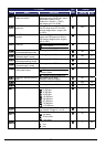
C130
Output [11] on delay
U
0.0 Sec.
C131
Output [11] off delay
Set range is 0.0 to 100.0 sec.
U
0.0 Sec.
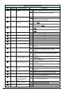
C132
Output [12] on delay
U
0.0 Sec.
C133
Output [12] off delay
Set range is 0.0 to 100.0 sec.
U
0.0 Sec.
C140
Relay output on delay
U
0.0 Sec.
C141
Relay output off delay
Set range is 0.0 to 100.0 sec.
U
0.0 Sec.
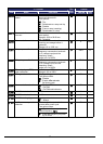
C142
Logic output 1 operand A
U
00
−
C143
Logic output 1 operand B
All the programmable functions
available for logic (discrete) outputs
except LOG1 to LOG3, OPO, no
U
00
−
C144
Logic output 1 operator Applies a logic function to calculate
[LOG] output state,
Three options:
00…[LOG] = A AND B
01…[LOG] = A OR B
02…[LOG] = A XOR B
U
00
−
C145
Logic output 2 operand A
U
00
−
C146
Logic output 2 operand B
All the programmable functions
available for logic (discrete) outputs
except LOG1 to LOG3, OPO, no
U
00
−