


19
Connecting to PLCs and Other Devices
Hitachi inverters (drives) are useful in many types of applications. During installation, the
inverter keypad (or other programming device) will facilitate the initial configuration. After
installation, the inverter will generally receive its control commands through the control
logic connector or serial interface from another controlling device. In a simple application
such as single-conveyor speed control, a Run/Stop switch and potentiometer will give the
operator all the required control. In a sophisticated application, you may have a
programmable logic controller (PLC) as the system controller, with several connections to
the inverter.
It is not possible to cover all the possible types of application in this manual. It will be
necessary for you to know the electrical characteristics of the devices you want to connect
to the inverter. Then, this section and the following sections on I/O terminal functions can
help you quickly and safely connect those devices to the inverter.
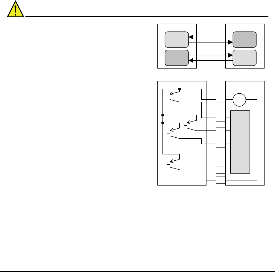
CAUTION: It is possible to damage the inverter or other devices if your application
exceeds the maximum current or voltage characteristics of a connection point.
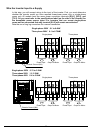
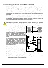
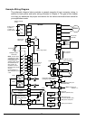
The connections between the inverter and
other devices rely on the electrical input/output
characteristics at both ends of each connection,
shown in the diagram to the right. The
inverter’s configurable inputs accept either a
sourcing or sinking output from an external
device (such as PLC). This chapter shows the
inverter’s internal electrical component(s) at
each I/O terminal. In some cases, you will
need to insert a power source in the interface
wiring.
In order to avoid equipment damage and get
your application running smoothly, we
recommend drawing a schematic of each
connection between the inverter and the other
device. Include the internal components of
each device in the schematic, so that it makes
a complete circuit loop.
After making the schematic, then:
1. Verify that the current and voltage for each
connection is within the operating limits of
each device.
2. Make sure that the logic sense (active high or active low) of any ON/OFF connection is
correct.
3. Check the zero and span (curve end points) for analog connections, and be sure the
scale factor from input to output is correct.
4. Understand what will happen at the system level if any particular device suddenly
loses power, or powers up after other devices.
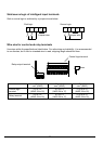
Other device
Input
circuit
Output
circuit
WJ200 inverter
Input
circuit
Output
circuit
signal
return
signal
return
Other device WJ200 inverter
Input
circuits
P24
1
2
3
7
L
24V
+ -
GND
…
…