


30
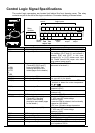
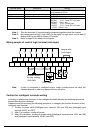
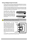
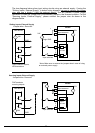
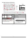
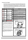
CAUTION: Be sure to diode in between "P24" and "PLC" when connecting plural
inverters with digital input wiring in common.
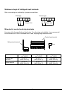
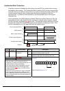
The power to the inverter control part can be supplied externally as shown below. Except
driving motor, it is possible read and write the parameters by keypad and via
communication even the drive itself is not powered.
By having ability inverter doesn’t block the current flowing into itself when it is not
powered. This may cause the closed circuit when two or more inverters are connected to
common I/O wiring as shown below to result in unexpected turning the on the input. To
avoid this closed circuit, please put the diode (rated:50V/0.1A) in the path as described
below.
Jumper
wire
Inserting
diode
P24
PLC
L
1
P24
PLC
L
1
Switch
OFF
Power ON
Power OFF
Input
ON
P24
PLC
L
1
P24
PLC
L
1
Switch
OFF
Power ON
Power OFF
Input
OFF
Jumper
wire
1
Switch
OFF
Switch
OFF
Input
OFF
Input
ON
P24
PLC
L
P24
PLC
L
P24
PLC
L
P24
PLC
L
1
1
1
Jumper
wire
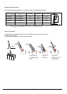
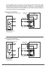
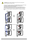
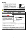
In case of Source logic
Jumper
wire