


38
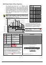
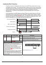
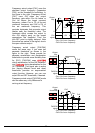
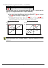
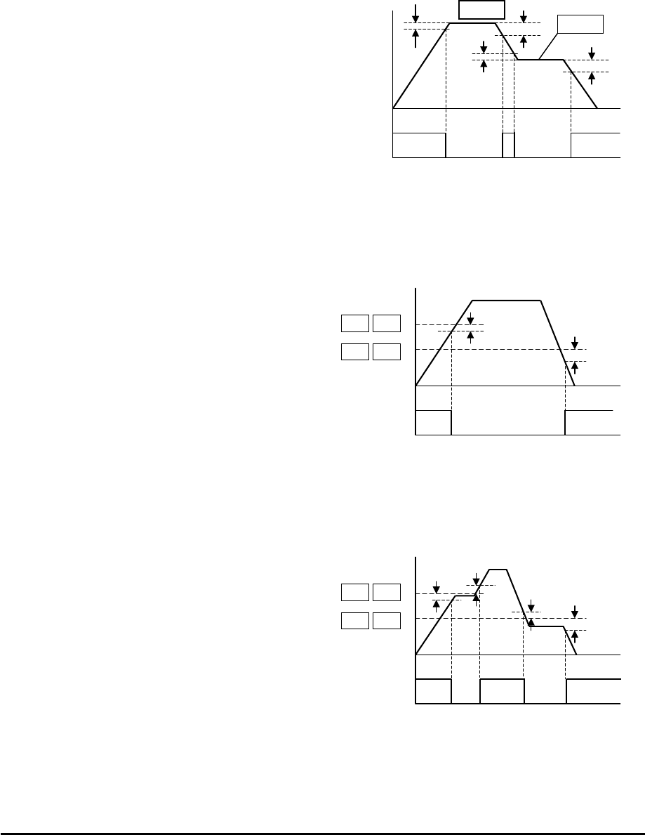
Frequency arrival output [FA1] uses the
standard output frequency (parameter
F001) as the threshold for switching. In
the figure to the right, Frequency Arrival
[FA1] turns ON when the output
frequency gets within Fon Hz below or
Fon Hz above the target constant
frequency, where Fon is 1% of the set
maximum frequency and Foff is 2% of
the set maximum frequency. This
provides hysteresis that prevents output
chatter near the threshold value. The
hysteresis effect causes the output to
turn ON slightly early as the speed
approaches the threshold. Then the
turn-OFF point is slightly delayed. Note
the active low nature of the signal, due to
the open collector output.
Frequency arrival output [FA2/FA4]
works the same way; it just uses two
separate thresholds as shown in the
figure to the right. These provide for
separate acceleration and deceleration
thresholds to provide more flexibility than
for [FA1]. [FA2/FA4] uses C042/C045
during acceleration for the ON threshold,
and C043/C046 during deceleration for the
OFF threshold. This signal also is active
low. Having different accel and decel
thresholds provides an asymmetrical
output function. However, you can use
equal ON and OFF thresholds, if desired.
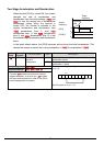
Frequency arrival output [FA3/FA5] works
also the same way, only difference is
arriving at set frequency.
FA1
signal
Output
freq.
Fon
F001
F001
Foff
Fon
ON
Foff
ON
0
Fon=1% of max. frequency
Foff=2% of max. frequency
FA2/FA4
signal
Output
freq.
thresholds
C042/C045
ON
0
C043/C046
Fon
Foff
Fon=1% of max. frequency
Foff=2% of max. frequency
FA3/FA5
signal
Output
freq.
thresholds
C042/C045
0
C043/C046
Fon
Foff
Fon=1% of max. frequency
Foff=2% of max. frequency
Foff
Fon
ON ON