


21
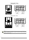
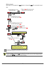
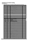
Control Logic Signal Specifications
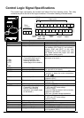
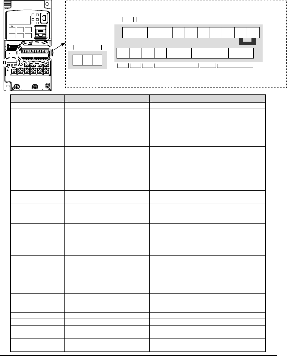
The control logic connectors are located just behind the front housing cover. The relay
contacts are just to the left of the logic connectors. Connector labeling is shown below.
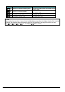
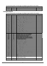
Terminal Name Description Ratings
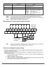
P24 +24V for logic inputs 24VDC, 100mA. (do not short to terminal L)
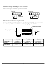
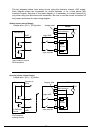
PLC Intelligent input common To change to sink type, remove the jumper
wire between [PLC] and [L], and connect it
between [P24] and [PLC]. In this case,
connecting [L] to [1]~[7] makes each input
ON. Please remove the jumper wire when
using external power supply.
1
2
3/GS1
4/GS2
5/PTC
6
7/EB
Discrete logic inputs
(Terminal [3],[4],[5] and [7]
have dual function. See
following description and
related pages for the details.)
27VDC max. (use PLC or an external supply
referenced to terminal L)
GS1(3) Safe stop input GS1
GS2(4) Safe stop input GS2
Functionality is based on ISO13849-1
See appendix for the details.
PTC(5) Motor thermistor input Connect motor thermistor between PTC and
L terminal to detect the motor temperature.
Set 19 in C005.
EB(7) Pulse train input B 2kHz max.
Common is [PLC]
EA Pulse train input A 32kHz max.
Common is [L]
L (in upper row) *1 GND for logic inputs Sum of input [1]~[7] currents (return)
11/EDM Discrete logic outputs [11]
(Terminal [11] has dual
function. See following
description and related pages
for the details.)
50mA max. ON state current,
27 VDC max. OFF state voltage
Common is CM2
In case the EDM is selected, the functionality
is based on ISO13849-1
4VDC max. ON state voltage depression
12 Discrete logic outputs [12] 50mA max. ON state current,
27 VDC max. OFF state voltage
Common is CM2
CM2 GND for logic output 100 mA: [11], [12] current return
AM Analog voltage output 0~10VDC 2mA maximum
EO Pulse train output 10VDC 2mA maximum, 32kHz maximum
L (in bottom row) *2 GND for analog signals Sum of [OI], [O], and [H] currents (return)
OI Analog current input 4 to 19.6 mA range, 20 mA nominal,
input impedance 100 Ω
Analog
out
p
ut
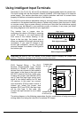
Logic inputs
Logic
out
p
ut
Jumper wire
PLC
Analog
in
p
ut
Pulse
Train
in
p
ut
Pulse
Train
out
p
ut
RS485
comm.
RS485
comm.
P24 1 L 3
2
5
4
6
SN 7
12 11 AM
CM2
OI
L
H
O
EA
SP EO
A
L2
A
L1
A
L0
Relay
contacts