


44
Analog Output Operation
In inverter applications it is useful to monitor the
inverter operation from a remote location or from the
front panel of an inverter enclosure. In some cases,
this requires only a panel-mounted volt meter. In other
cases, a controller such as a PLC may provide the
inverter’s frequency command, and require inverter
feedback data (such as output frequency or output
current) to confirm actual operation. The analog output
terminal [AM] serves these purposes.
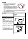
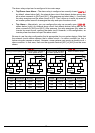
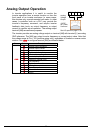
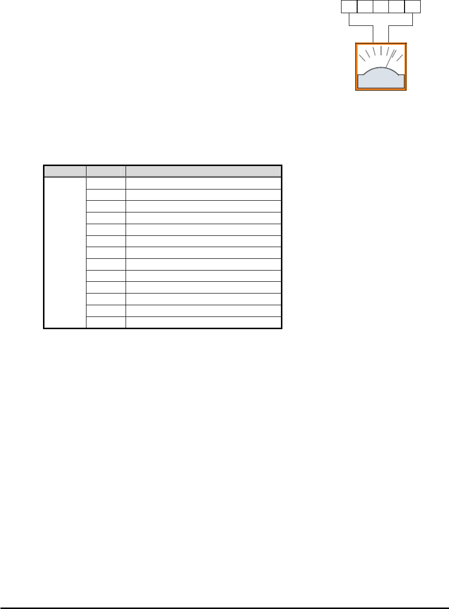
The inverter provides an analog voltage output on terminal [AM] with terminal [L] as analog
GND reference. The [AM] can output inverter frequency or current output value. Note that
the voltage range is 0 to +10V (positive-going only), regardless of forward or reverse motor
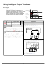
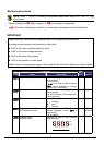
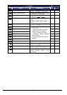
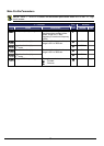
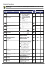
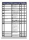
rotation. Use C028 to configure terminal [AM] as indicated below.
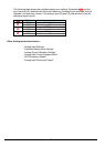
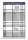
Func. Code Description
00
Inverter output frequency
01
Inverter output current
02
Inverter output torque
03
Digital output freqnency
04
Inverter output goltage
05
Inverter input power
06
Electronic Thermal Load
07
LAD frequency
08
Digital current monitor
10
Cooling fin temperature
12
General purpose
15
Pulse train
C028
16
Option
AM H O OI L
+-
A
GND
A
nalog
Voltage
Output
10VDC
full scale,
2mA max
See I/O specs on page 21,22