


Return to Section TOC Return to Section TOC Return to Section TOC Return to Section TOC
Return to Master TOC Return to Master TOC Return to Master TOC Return to Master TOC
TROUBLESHOOTING & REPAIR
F-45 F-45
LN-9 Wire Feeder
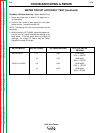
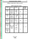
OUT OF VOLTAGE RANGE SHUT DOWN TEST (continued)
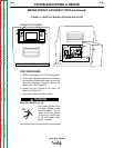
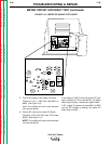
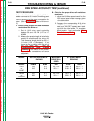
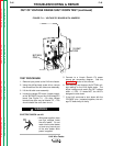
FIGURE F.11 – VOLTAGE PC BOARD WITH JUMPERS
BYPASS
PINS
1/8 AMP
FUSE
TEST PROCEDURE
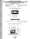
1. Remove input power to the LN-9 wire feeder.
2. Using the phillips head screw driver, remove
the screws from the left side cover assembly.
3. Lift the left side cover assembly.
4. Locate the voltage PC board. Jumper togeth-
er the "BYPASS" pins on the LN-9 voltage PC
board. See Figure F.11. (On older voltage
boards these pins may be labeled "B".) This
should disable the shut down circuit.
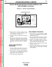
ELECTRIC SHOCK can kill.
• With power applied, there
are high voltages inside
the wire feeder. Do not
reach into the wire feeder
or touch any internal part
of the wire feeder while
power is applied.
5. Connect to a Lincoln Electric CV power
source per connection diagram. See the
Installation
section of this manual.
6. Start welding and observe the ACTUAL volt-
age reading on the LN-9 digital meter. The
actual voltage must match the SET voltage
within +/- 0.5V. If it does NOT, the LN-9 is
designed to shut down.
7. If the LN-9 continues to shut down with the
"BYPASS" pins jumpered together, the volt-
age PC board may be faulty.
WARNING