


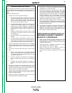

INSTALLING THE LN-9N and LN-9S
2-ROLL AND 4-ROLL MODELS
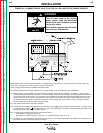
ATTACHING THE WIRE REEL STAND
Both 2-Roll and 4-Roll LN-9 model wire feeders are
shipped without a wire reel stand. The screws and
washers for mounting a wire reel stand are included
with the LN-9 (fastened in their respective mounting
holes). To attach a stand:
1. Remove the three 3/8" hex screws from the back of
the wire feed unit.
2. Place the wire reel stand mounting bracket in posi-
tion against the back of the wire feed unit.
3. Replace and tighten the screws. The long screw
and plain washer go into the top hole.
MOUNTING THE UNIT
LN-9N model wire feeders can be mounted directly on
top of their power source as long as it is secure and
level. When portability is required, the LN-9 can be
mounted on a K163 undercarriage See the
Accessories
section for details.
A K178-1 swivel platform is available for mounting the
LN-9 to the power source. See the
Accessories
sec-
tion for details.
INSTALLING THE LN-9F
2-ROLL AND 4-ROLL MODELS
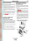
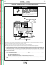
MOUNTING THE WIRE FEED UNIT
Mount the wire feed unit by means of the insulated
mounting bracket attached to the bottom of the gear-
box. The gearbox assembly is electrically "hot" when
the gun trigger is pressed. Therefore, make certain the
gearbox does not come in contact with the structure on
which the unit is mounted. The wire feed unit should
be mounted so that the drive rolls are in a vertical plane
so dirt will not collect in the drive roll area. Position the
mechanism so it will point down at about a 45
o
angle so
the wire feed gun cable will not be bent sharply as it
comes from the unit.
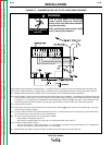
MOUNTING THE CONTROL BOX
The same control box is used for both the 2-Roll and 4-
Roll wire feed unit. It contains two keyhole slots and
one slot for mounting. Mount the box at some conve-
nient location close to the wire feed unit. This will
enable the 16-foot control cable assembly supplied
with both the LN-9F 2-Roll and 4-Roll to reach between
the control box and the wire feed unit.
1. Drill the required holes in the mounting surface.
Partially install 1/4-20 screws.
2. Open the control box door by removing the two door
screws.
3. Mount the box.
4. Tighten the screws.
5. Close the control box door and replace the door
screws.
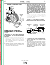
CONNECTING THE WIRE FEED UNIT TO
THE CONTROL BOX
Both the LN-9F 2-Roll and 4-Roll include the same 16
ft. control and electrode cable assembly. Connect the
wire feed unit to the control box as follows:
1. Make certain the cables are protected from any
sharp corners that may damage their jackets.
Mount the cable assembly along the boom so the
end with the female amphenol connector pins is at
the wire feed unit.
2. Connect the cable connectors to the receptacles on
the back of the wire feed unit connection box.
3. At the same end, connect the electrode lead to the
connection stud of the copper strap along the side
of the wire feed unit.
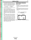
4. At the control box end, connect the amphenol con-
nectors of the control cable to the mating MS-type
receptacles on the bottom of the control box. (See
Figure A.4,
later in this section, for the location of
this connection.)
INSTALLATION
A-3 A-3
LN-9 Wire Feeder
Return to Section TOC Return to Section TOC Return to Section TOC Return to Section TOC
Return to Master TOC Return to Master TOC Return to Master TOC Return to Master TOC