


MAKING A TEST WELD AND
ADJUSTING LN-9 RESPONSE
AND
STARTING CHARACTERISTICS
ADJUST THE POWER SOURCE
DC-250, DC-400, or DC-600*
1. Connect electrode lead to terminal of desired
polarity.
2. Set toggle switch to same polarity as the electrode
cable connection.
3. Set toggle switch to "Output Control Remote."
4. Set mode switch to the desired position for the
process to be used.
* DC-600 codes 8288 and above are preferred.
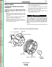
CV-400, CV-500-I
1. Connect electrode lead to terminal of desired
polarity.
2. Connect #21 control lead to the work polarity ter-
minal (+21 or -21), at the terminal strip, matching
the same polarity as the work cable connection.
3. Set toggle switch to "Output Control Remote."
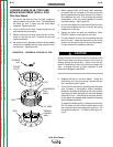
R3S-400, R3S-600, R3S-800
1. Connect electrode lead to terminal of desired
polarity.
2. Set toggle switch to same polarity as the electrode
cable connection.
3. Set the toggle switch to "Remote."
4. Install voltage triangle to a position as close as
possible to desired arc voltage. See
Automatic
Shutdown
in the Operation section.
NOTE: Since the LN-9 cannot control the fixed
OCV of R3S power sources, starting diffi-
culties may be experienced when striking
the arc of processes which use a low volt-
age or a narrow voltage range. The fol-
lowing steps should remedy this difficulty:
1 . The electrode stickout when starting should be
as close to procedural length as possible, and
the tip of the electrode should be clean and
held nearly touching the work.
2. Install the R3S voltage triangle to the position
higher than the desired arc voltage, provided it
does not result in out of range shutdown of the
LN-9 while welding. See
Automatic
Shutdown
in the Operation section of this
manual.
SAM
1. Set "Electrode Polarity" switch to the appropriate
"Constant Voltage" or "Variable Voltage" position of
the desired polarity for the process being used on
the SAM-400, or set desired polarity on the SAM-
650.
2. Set the toggle switch to "Constant Voltage."
3. Set the "Constant Voltage Control" rheostat to
Number 5 for Innershield and other open arc
processes. (Use the maximum slope Innershield
tap of SAM-650.) Set the "Constant Voltage
Control" rheostat to Number 7 and the "Current
Control" rheostat to 500 for CV subarc processes.
(Use 300-575 tap of SAM-650.)
PULSE POWER 500, DC650 PRO
Refer to each machine Instruction Manual. The LN-9
requires the K442-1 Pulse Power Filter Kit. For LN-9
codes below 9100, use kit K442-2. (See the
Accessories
section of this manual.)
OPERATION
B-18 B-18
LN-9 Wire Feeder
Return to Section TOC Return to Section TOC Return to Section TOC Return to Section TOC
Return to Master TOC Return to Master TOC Return to Master TOC Return to Master TOC