


GUN AND CABLE MAINTENANCE
For instructions on periodic maintenance for the weld-
ing gun and cables, refer to the manual for your specif-
ic model of welding gun. Also see IM-294.
GUN CABLE CONNECTOR
REQUIREMENTS TO PERMIT PROPER
CONNECTION TO LINCOLN LN-9 AND
LN-9F WIRE FEEDER
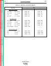
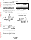
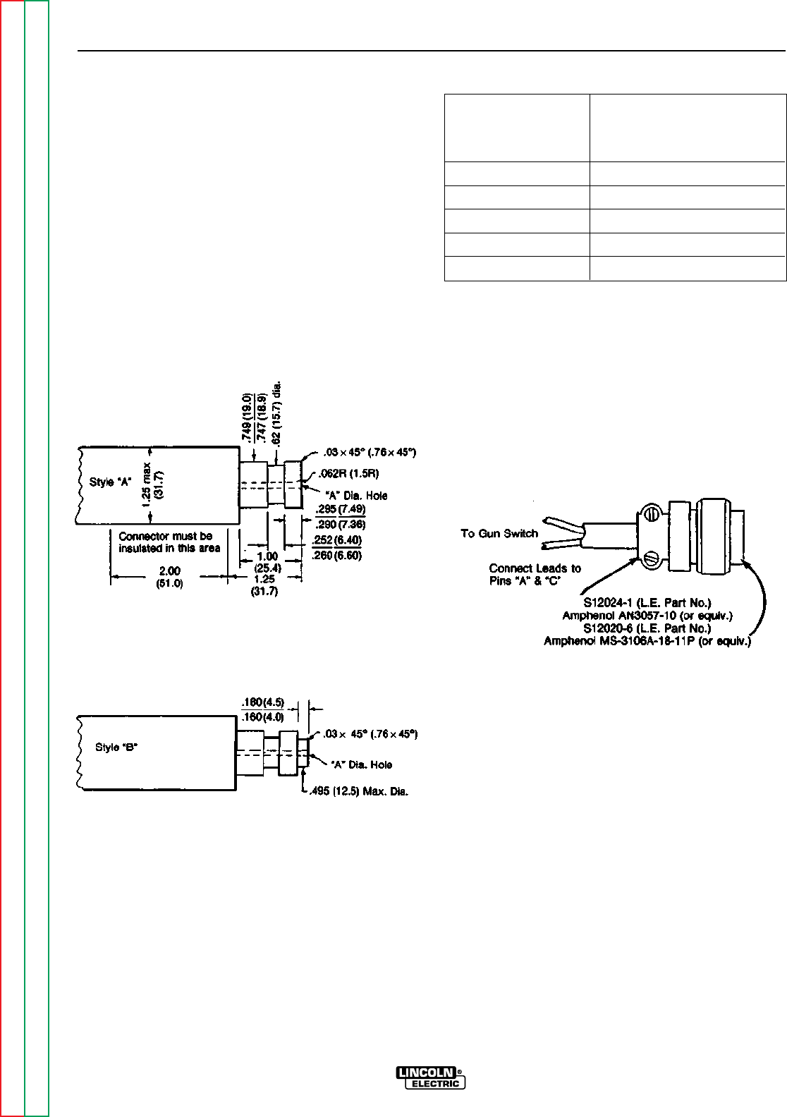
The following Figures D.1 and D.2 should serve as a
guide to determine if a particular gun or switch can be
connected to the LN-9 and LN-9F models.
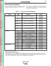
“A” Diameter Hole
to be Concentric to
Wire Size .749/.747 Dia.
Within .008 F.I.M.
7/64 & .120" .152 (#24 Drill)
.068 Thru 3/32" .125 (1/8 Drill)
1/16 or .062" .078 (5/64 Drill)
.045 & .052" .062 (1/16 Drill)
.030 & .035" .055 (#54 Drill)
All dimensions in inches and (millimeters).
1/2 Amp AC 24 Volts — Inductive
1/2 Amp DC 24 Volts — Inductive
MAINTENANCE
D-3 D-3
LN-9 Wire Feeder
Return to Section TOC Return to Section TOC Return to Section TOC Return to Section TOC
Return to Master TOC Return to Master TOC Return to Master TOC Return to Master TOC
FIGURE D.1 – LN-9 CONNECTORS
LN-9 CONNECTOR FOR 1/16-120” (1.6-3.0 MM) WIRE)
FIGURE D.2 – SWITCH REQUIREMENTS
LN-9 CABLE CONNECTOR FOR .030-.052” (0.8-1.3 mm)
WIRE (FOR ALL OTHER DIMENSIONS, SEE DIAGRAM
ABOVE).
NOTE: Connector part with .7459/.747 (19.0/18.9)
diameter should be made from brass if it is to be part
of the welding current carrying circuit.