


Return to Section TOC Return to Section TOC Return to Section TOC Return to Section TOC
Return to Master TOC Return to Master TOC Return to Master TOC Return to Master TOC
INSTALLATION
A-9 A-9
LN-9 Wire Feeder
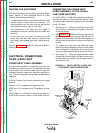
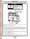
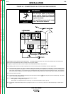
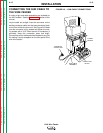
FIGURE A.6 – CONNECTION OF LN-9 TO DC-600 POWER SOURCES
Above diagram shows electrode connected positive. To change polarity, turn power off, reverse the electrode and work leads at the
power source and position the switch on power source to proper polarity.
For optimum performance with the LN-9, DC-600’s with codes 8288 and above are preferred.
N.B. Welding cables must be of proper capacity for the current and duty cycle of immediate and future applications.
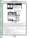
N.C. Extend lead #21 using #14 or larger insulated wire physically suitable for the installation. An S16586-[ ] remote voltage sensing
work lead is available for this purpose. Connect it directly to the work piece keeping it electrically separate from the welding work
lead circuit and connection. For convenience, this extended #21 lead should be taped to the welding work lead. (This extended
#21 lead connection replaces the need to employ the remote work lead accessory on LN-9’s which have a direct work lead jack.)
N.D. Tape up bolted connection.
N.E. Connect the LN-9 control cable ground lead to the frame terminal marked near the power source terminal strip. The power
source must be properly grounded.
N.G. The LN-9 voltage control jumpers must be connected as follows:
White jumper on voltage board to pin “S”.
Blue jumper on voltage board (Later units only) or on start board (Earlier units) to pin “B”.
N.H. For DC-600 Codes below 8200 connect a jumper from “N” to “P” on LN-9 only. There is no NPS terminal strip on codes above
8200.
WARNING
• Turn off input power to the welding
power source using the disconnect
switch at the fuse box before connect-
ing the wire feeder
• Only qualified persons should install,
use or service this machine.
ELECTRIC SHOCK
can kill.