


TROUBLESHOOTING & REPAIR
F-46 F-46
LN-9 Wire Feeder
Return to Section TOC Return to Section TOC Return to Section TOC Return to Section TOC
Return to Master TOC Return to Master TOC Return to Master TOC Return to Master TOC
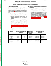
OUT OF VOLTAGE RANGE SHUT DOWN TEST (continued)
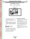
8. If the ACTUAL voltage reading is zero, the
sensing leads may be faulty. Check the con-
tinuity (zero ohms) of leads #21 and #67.
Lead #21 must have continuity to the work-
piece, and #67 must have continuity to the
electrode. Also check the 1/8 amp fuse on
the voltage PC board.
9. Check the polarity switches in the LN-9 and
the Lincoln power source and their associat-
ed leads. Set the switches to the same
polarity as the electrode. See the Wiring
Diagram.
10. If the ACTUAL voltage reading is different
from the SET voltage reading, the power
source may not be capable of producing the
required arc voltage, the control cable may
be faulty or misconnected, or the LN-9 volt-
age PC board may be faulty.
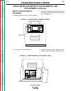
11. After all tests are complete, remove input
power to the wire feeder and remove the
jumper you placed on the "BYPASS" pins on
the voltage PC board. Reattach the left case
side cover assembly.