


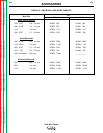
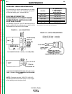
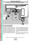


POWER INPUT CIRCUITS
The 115VAC is applied (usually from the welding power
source) via the input connector and through the circuit
breaker and R1 resistor to the power board, the T2 trig-
ger transformer, and the T1 transformer.
The 24VAC developed at the T2 trigger transformer is
applied to the trigger board. There it is rectified and
regulated to 20VDC and used to operate the wire feed-
er trigger circuitry.
The 28VAC produced by the T1 transformer secondary
is applied to the power board. There it is rectified and
regulated to 15VDC. This 15VDC powers the electron-
ics on the power, control, and voltage boards. The
10VAC secondary voltage is rectified, regulated, and
utilized by the meter board.
THEORY OF OPERATION
E-2 E-2
LN-9 Wire Feeder
Return to Section TOC Return to Section TOC Return to Section TOC Return to Section TOC
Return to Master TOC Return to Master TOC Return to Master TOC Return to Master TOC
FIGURE E.2 – POWER INPUT CIRCUITS
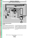
NOTE: Unshaded areas of Block Logic Diagram are the subject of discussion.
INPUT
CONNECTOR
TO
VOLTAGE
BOARD
TO
CONTROL
BOARD
METER
BOARD
VOLTS
SPEED
SWITCH
T1
CIRCUIT
BREAKER
R1
TRIGGER
CONNECTOR
TRIGGER
BOARD
F
U
S
E
T2
WIRE FEED
MOTOR
THERMOSTAT
C
O
N
T
R
O
L
B
O
A
R
D
VOLTAGE
BOARD
P
O
W
E
R
B
O
A
R
D
GROUND
LEAD
PROTECTOR
WIRE
FEED
MOTOR
TACH
BOARD
WIRE
SPEED
CONTROL
VOLTAGE
CONTROL
POLARITY
SWITCH
VOLTAGE SENSING
VOLTAGE CONTROL
POWER SOURCE OUTPUT TRIGGER (#2 )
S
H
U
T
D
O
W
N
+ 15VDC
+ 15VDC
WIRE SPEED CONTROL
GEAR
BOX
TRIGGER SIGNAL
TRIGGER SIGNAL
R
E
F
E
R
E
N
C
E
V
O
L
T
A
G
E
WORK
ELECTRODE VOLTAGE SENSING
24VAC
28VAC
10VAC
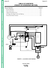
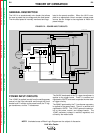
GENERAL DESCRIPTION
The LN-9 is a semiautomatic wire feeder that allows
the user to preset the arc voltage and wire feed speed.
The wire feed speed is internally monitored and regu-
lated to the preset condition. When the LN-9 is cou-
pled to an appropriate Lincoln constant voltage power
source, the arc voltage is also regulated to match the
preset voltage.