


Return to Section TOC Return to Section TOC Return to Section TOC Return to Section TOC
Return to Master TOC Return to Master TOC Return to Master TOC Return to Master TOC
TROUBLESHOOTING & REPAIR
F-48 F-48
LN-9 Wire Feeder
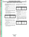
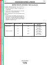
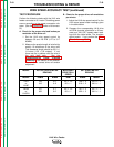
GENERAL POWER SUPPLY TESTS (continued)
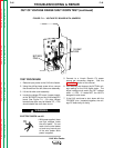
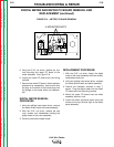
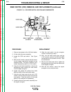
TEST PROCEDURE
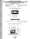
1. Remove input power to the LN-9 wire feeder.
2. Using the phillips head screw driver, remove
the screws from the left side cover assembly.
3. Lift the left side cover assembly.
4. Locate the power PC board and the control
PC board in the wire feeder main assembly;
locate the voltage PC board in the left side
cover.
ELECTRIC SHOCK can kill.
• With power applied, there
are high voltages inside
the wire feeder. Do not
reach into the wire feeder
or touch any internal part
of the wire feeder while
power is applied.
5. Apply power (115VAC) to the wire feeder at
the correct pins. See the Wiring Diagram.
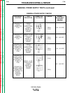
6. Perform the power supply checks as
described in the table below. If any of the
readings are incorrect (out of range) or miss-
ing, the power PC board may be faulty.
NOTE: Do NOT unplug the Molex connector.
7. Also perform the
T1 Transformer Test.
WARNING