


F-63 F-63
LN-9 Wire Feeder
Return to Section TOC Return to Section TOC Return to Section TOC Return to Section TOC
Return to Master TOC Return to Master TOC Return to Master TOC Return to Master TOC
TROUBLESHOOTING & REPAIR
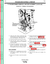
TACH PC BOARD REMOVAL AND REPLACEMENT (continued)
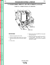
REASSEMBLY
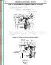
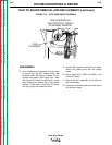
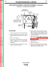
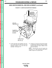
8. Upon reassembly the spacers must be used
to assure that the disc rotates freely and
smoothly within the sensor "window" on the
printed circuit board. See Figure F.24. Note
that the tach PC board must be held in place
when aligning the rotating disc in the sensor
window. Press down on the tach PC board
with your finger to simulate the cover.
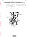
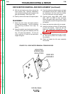
9. Use the 3/8" wrench to hold the nut in place.
Attach the rotating disc with the phillips
screw.
10. Attach leads #510, #525, and #555 to the
control PC board.
11. Secure the tach assembly cover with two
slot head screws.
12. Replace the left side case cover and secure
with phillips screws.
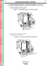
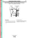
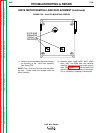
FIGURE F.24 – TACH COMPONENT ASSEMBLY
USE SPACERS SO
DISC ROTATES FREELY
IN SENSOR WINDOW
TACH
PC BOARD