


F-68 F-68
LN-9 Wire Feeder
Return to Section TOC Return to Section TOC Return to Section TOC Return to Section TOC
Return to Master TOC Return to Master TOC Return to Master TOC Return to Master TOC
TROUBLESHOOTING & REPAIR
DRIVE MOTOR REMOVAL AND REPLACEMENT (continued)
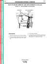
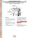
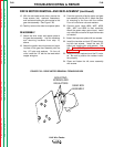
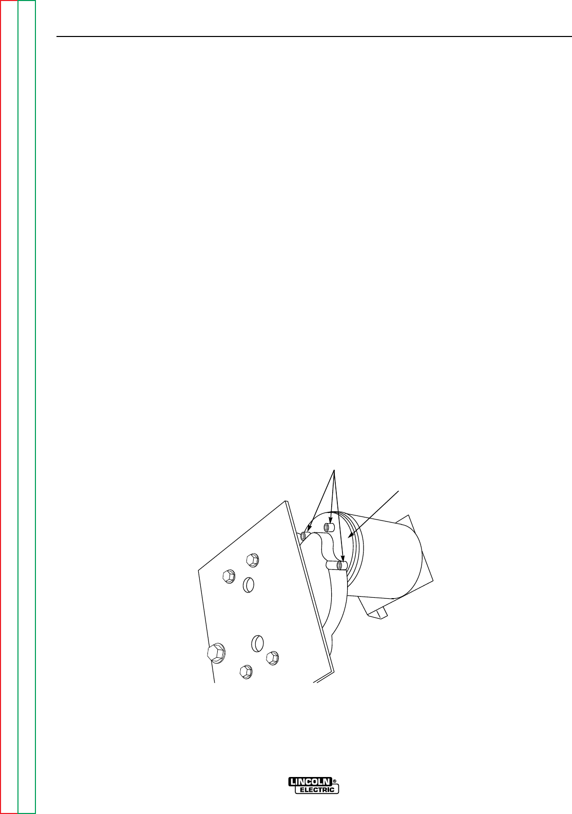
15. With the slot head screw driver, remove the
three screws, lock washers, flatwashers,
and insulators holding the drive motor to the
gear box assembly. See Figure F.28.
16. Carefully remove the motor and spacer plate.
REASSEMBLY
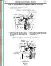
17. Attach the drive motor and spacer plate to
the gear box assembly. Use the insulators
and mounting hardware from step 15,
above.
18. Attach the glastic mounting board and mylar
insulator to the gear box assembly with the
four 1/2" bolts and washers. On four-roll
units, install the 1/2" bolt for the reed switch
copper energizer.
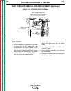
19. From the right side, slide the motor and gear
box assembly into the LN-9. Attach the glas-
tic mounting to the floor with the screws.
Four-roll units have nuts and washers.
20. Connect motor leads #626, #627, #539,
#541, #527 and #528 to their terminals.
Attach the green motor ground lead. Install
any cable ties cut earlier or tape the harness
as needed.
21. Attach the top motor plate with two screws.
22. Install the insulator and tach PC board hous-
ing with two screws. Install the tach PC
board and rotating disc and spacers. See
the
Tach PC Board Removal and
Replacement
procedure.
23. Install the 9-pin amphenol and the R1 resis-
tor. Be sure to position the resistor insula-
tors properly.
24. Close and fasten the left cover assembly
with screws.
FIGURE F.28 – DRIVE MOTOR REMOVAL FROM GEAR BOX
MOUNTING
SCREWS AND
INSULATORS
GEAR BOX
ASSEMBLY