


TROUBLESHOOTING & REPAIR
F-29 F-29
LN-9 Wire Feeder
Return to Section TOC Return to Section TOC Return to Section TOC Return to Section TOC
Return to Master TOC Return to Master TOC Return to Master TOC Return to Master TOC
T2 TRANSFORMER TEST (continued)
Electric Shock can kill.
• With power applied,
there are high voltages
inside the wire feeder.
Do not reach into the
wire feeder or touch any
internal part of the wire
feeder while power is
applied.
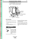
7. Insulate the T2 transformer primary leads
#531 and #32A and apply 115 VAC power.
See the Wiring Diagram and
Figure F.4.
8. Using the volt/ohmmeter, check for approx-
imately 24VAC at the T2 transformer sec-
ondary leads #621 and #620. Place the
probes where the leads connect on the trig-
ger PC board. See Figure F.5.
9. With 115VAC applied to the primary leads
#531 and #32A, if the secondary voltage is
missing or low the T2 transformer may be
faulty. Replace the T2 transformer.
10. After the test is completed, disconnect the
115VAC from the T2 transformer primary
leads #531 and #32A. Reconnect lead #32
to the circuit breaker. Re-attach the
Protection Circuit Troubleshooting name-
plate. Close the right and left side cover
assemblies and replace all previously
removed screws.
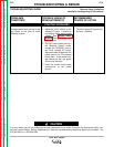
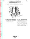
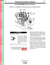
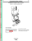
FIGURE F.5 – T2 SECONDARY LEADS #621 AND #620 ON TRIGGER PC BOARD
LEAD
621
TRIGGER
PC BOARD
LEAD
620
WARNING